|
| |
TM 9-2320-356-BD
5.
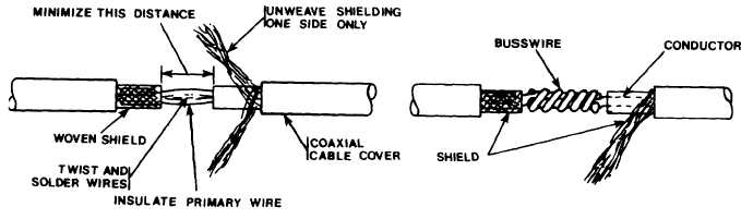
Insulate wire splice with several
6.
Lay the unwoven shielding over the insul
woven shield on the other side.
D i s t r i b u te
the diameter of the wire and solder or wrap
layers of tape.
ated splice and make contact with the
the unwoven shielding carefully around
with busswire.
7.
Cover the entire splice with several layers of tape.
8.
Record the BDAR action taken.
When the mission is completed, as soon as
practicable, repair using standard maintenance procedures.
Option 2:
Shrink Tube Insulation.
1.
Prepare the severed ends of the cable as shown.
2.
Slide shrinkable or flexible transparent tubing over the splice. The sleeve
must be long enough to extend beyond the two ground sheath connectors.
3. Attach a grounding sheath connector to one end of the severed wire and crimp.
4.
Install a grounding sheath connector to the other side of the break. Do not
crimp this one yet.
5.
Use a permanent splice to join the severed inner conductor or use the barrel of
a terminal lug when a permanent splice is not available.
A ballpoint pen refill
will work as a terminal splice; crimp onto wires.
Insulate from the shielding.
6.
Push the free end of the grounding wire into the uncrimped grounding sheath
connector and crimp securely.
8-7
|