 |
|||
|
|
|||
|
Page Title:
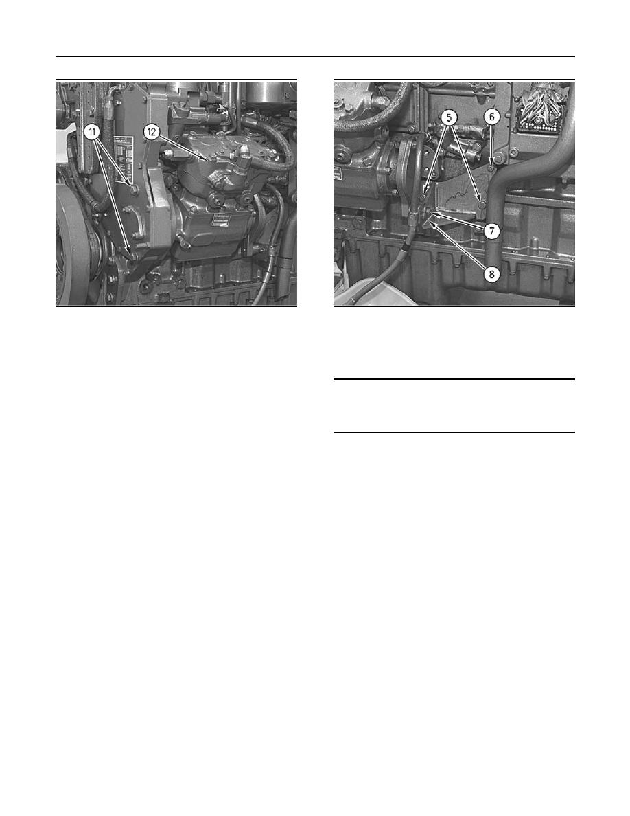
Illustration 287 Schematic Drawing |
|
||
| ||||||||||
|
|
 113
TM 9-2320-312-24-2
Truck Engine
Disassembly and Assembly Section
g00705313
g00609684
Illustration 287
Illustration 288
1. Install Tooling (A) and a proper lifting device
to the air compressor. The weight of the air
and install bolts (5) and (6). Install the spacer
compressor is approximately 23 kg (51 lb).
and bolt (7). Hand tighten all bolts.
2. Inspect the condition of the gasket. Replace the
NOTICE
gasket, if necessary. Install the gasket between
A loose compressor bracket can lead to a broken front
air compressor (12) and the timing gear housing.
cover and can cause damage to the front gear train of
the engine.
Ensure that the drive gear engages correctly
with the gear in the front housing.
b. Tighten bolt (7) to a torque of 50 10 Nm
(37 7 lb ft). Tighten bolt (5) to a torque of
4. Apply 9S-3263 Thread Lock Compound to the
55 10 Nm (40 7 lb ft). Tighten bolt (6) to
threads of two bolts (11). Install two bolts (11).
a torque of 28 7 Nm (21 5 lb ft). Remove
Tighten bolts (11) to a torque of 100 20 Nm
the lifting device and Tool (A).
(75 15 lb ft).
6. Install the mounting bracket for Bendix Tu-Flo
5. Install the mounting bracket for a Midland EL-740
550 and Bendix Tu-Flo 750 air compressors by
air compressor by using the following procedure:
using the following procedure:
|
|
Privacy Statement - Press Release - Copyright Information. - Contact Us |
