 |
|||
|
|
|||
|
Page Title:
Test Step 2. Inspect Electrical Connectors and Wiring |
|
||
| ||||||||||
|
|
 393
TM 9-2320-312-24-2
Troubleshooting Section
Test Step 2. Inspect Electrical Connectors
Expected Result:
and Wiring.
All connectors, pins and sockets should be
completely coupled and/or inserted and the harness
and wiring should be free of corrosion, abrasion
or pinch points.
Results:
OK Proceed to Test Step 3.
Not OK
Repair: Perform the following repair:
Repair the connectors or wiring and/or replace
the connectors or wiring. Ensure that all of the
seals are properly in place and ensure that the
connectors are completely coupled.
Verify that the repair eliminates the problem.
STOP.
Test Step 3. Check the Service Brake
Pedal Switch 2 Status on the Electronic
Service Tool.
Table 199
Table for Status of the Service Brake Pedal Position
Switch Position or
Status
Circuit
Pedal Position
The Service Brake Pedal
OFF
Open
is DEPRESSED.
The Service Brake Pedal
ON
Closed
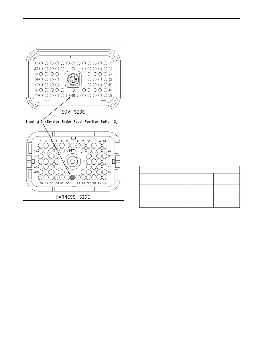
g00770850
is RELEASED.
Illustration 170
A. Thoroughly inspect ECM vehicle harness
A. Access the electronic service tool status screen.
connector J1/P1, the firewall bulkhead connector
and the terminal 64 (service brake pedal position
B. Turn the ignition key switch to the ON position.
(switch 2)).
C. Start the engine. Ensure that the air system
Refer to Troubleshooting, "Electrical Connectors
is charged if the vehicle is equipped with air
- Inspect" for details.
brakes. Depress the service brake while the
status of the service brake pedal position (switch
B. Perform a 45 N (10 lb) pull test on each of the
2) is being observed. Also, release the service
wires in the ECM connector that are associated
brake while the status of the service brake pedal
with the switches.
position (switch 2) is being observed.
Refer to Illustration 170.
Refer to Table 199 for the status of the switch or
for the status of the pedal position.
C. Check the ECM connector (allen head screw) for
the proper torque of 6.0 Nm (55 lb in).
Note: If the status indicates "Not Installed", check
the programming of the "Transmission Style". This
D. Check the harness and wiring for abrasion and
parameter must be programmed to "Automatic
pinch points from the sensor to the ECM.
Option 2", "Automatic Option 3", "AT/MT/HT Option
2", or "AT/MT/HT Option 3".
|
|
Privacy Statement - Press Release - Copyright Information. - Contact Us |
