 |
|||
|
|
|||
|
Page Title:
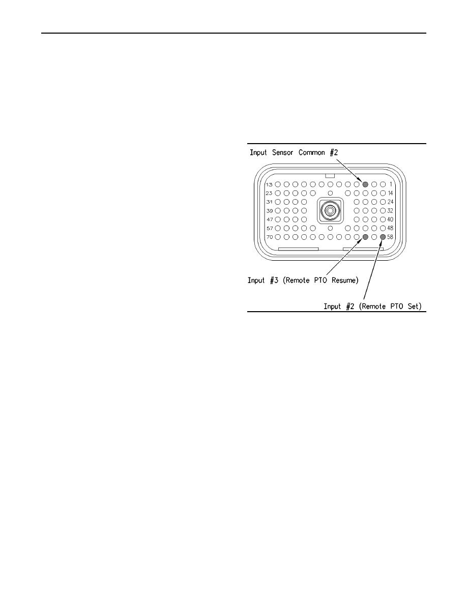
Illustration 158 ECM Breakout T-connector |
|
||
| ||||||||||
|
|
 360
TM 9-2320-312-24-2
Troubleshooting Section
7. If the problem returns with the suspect ECM,
Refer to Illustration 157.
replace the ECM.
Expected Result:
8. Verify that the repair eliminates the problem.
The switch status of the cruise control set/resume
STOP.
switch on ET behaves in the following manner:
Test Step 8. Check the Status of the
The switch status of the cruise control set/resume
Remote PTO Set Switch and the Remote
switch is "OFF" when the jumper is removed.
PTO Resume Switch on ET.
The switch status of the cruise control set/resume
switch changes from "OFF" to set switch "ON"
when the jumper is connected from terminal
35 (Set) to terminal 5 (AP sensor/switch sensor
common).
The switch status of the cruise control set/resume
switch changes from "OFF" to resume switch
"ON" when the jumper is connected from terminal
44 (switch resume terminal) to terminal 5 (AP
sensor/switch sensor common).
Results:
Yes The set input and the resume input of the
ECM are functioning correctly. The problem is in
the switches of the vehicle or the problem is in
the wiring of the vehicle.
Repair: Inspect the wiring. Select one of the
following options:
g00768769
Illustration 158
Repair the wiring or replace the wiring.
ECM Breakout T-connector
Send the vehicle to the OEM dealer for repair.
A. Turn the ignition key switch to the OFF position.
Verify that the repair eliminates the problem.
B. Fabricate a jumper wire 100 mm (4 inch) long.
Crimp a Deutsch pin to both ends of the wire.
STOP.
C. Disconnect vehicle harness connector P1 from
No The ECM is not reading the switch status
the ECM.
change.
D. Connect a breakout T to ECM connector J1 and
Repair: Perform the following diagnostic
connect P1 to the breakout T.
procedure:
E. Connect ET to the cab data link connector.
1. Temporarily connect a test ECM.
F. Turn the ignition key switch to the ON position.
2. Ensure that the "PTO Configuration" of the test
ECM matches the "PTO Configuration" of the
G. Access the Remote PTO Set Switch and Remote
suspect ECM.
PTO Resume Switch status on ET.
H. While the status of the Remote PTO Set Switch is
being observed on ET, install the jumper into the
4. Recheck the system for active diagnostic
breakout T in order to connect terminal 58 (input
codes.
2) to terminal 3 (input sensor common #2). Also,
while the switch status is being observed on ET
5. Repeat the test step.
remove the jumper from the breakout T in order
to disconnect terminal 58 (input 2) from terminal
6. If the problem is resolved with the test ECM,
3 (input sensor common #2).
reconnect the suspect ECM.
|
|
Privacy Statement - Press Release - Copyright Information. - Contact Us |
