 |
|||
|
|
|||
|
Page Title:
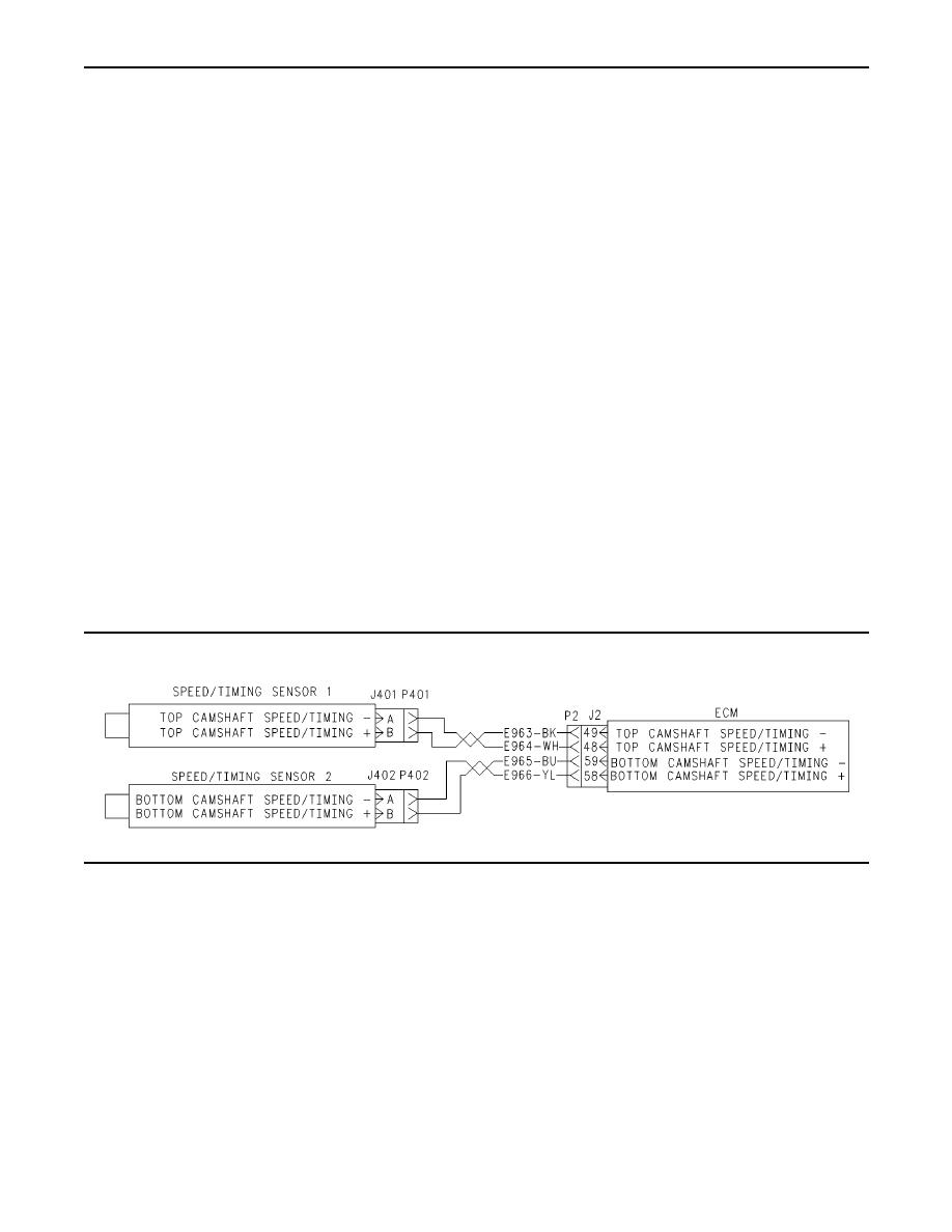
Illustration 91 Circuit schematic for the speed/timing sensors |
|
||
| ||||||||||
|
|
 255
TM 9-2320-312-24-2
Troubleshooting Section
If a replacement of the ECM is required, the
ECM parameters and the timing calibration can
be transferred from the suspect ECM to the
replacement ECM. Timing calibration will not be
necessary. This feature requires an electronic
service tool and this feature is only possible if the
existing ECM can communicate with the electronic
service tool. Use the procedure "Copy Configuration
- ECM Replacement" on the electronic service
tool. Refer to Troubleshooting, "Programming
Parameters" for more information.
When the sensors are being installed, complete
all of the following tasks:
Lubricate the O-ring with oil.
Ensure that the sensor has a face seal inside the
connector body. If a seal is damaged or missing,
replace the seal.
Ensure that the sensor is fully seated into the
engine before tightening the bracket bolt.
Ensure that the connector is latched on both
sides.
Ensure that the harness is properly secured,
and ensure that the harness is attached to the
harness clip.
g00866705
Illustration 91
Circuit schematic for the speed/timing sensors
Test Step 1. Connect the Electronic
64-11 No Pattern on Speed Sensor #2 (34)
Service Tool and Note all Active
Diagnostic Codes and Logged Diagnostic
190-02 Loss of Engine RPM Signal (34)
Codes
190-11 No Pattern on Speed Sensor #1 (34)
A. Connect the electronic service tool to the cab
data link connector.
B. Turn the ignition key switch to the ON position.
C. Check for one of the following logged diagnostic
codes or active diagnostic codes:
64-02 Loss of Engine RPM Signal #2 (34)
|
|
Privacy Statement - Press Release - Copyright Information. - Contact Us |