 |
|||
|
|
|||
|
Page Title:
Fuel Heater And Water Separator (If Equipped) |
|
||
| ||||||||||
|
|
 43
TM 9-2320-312-24-2
Systems Operation Section
Fuel Heater And Water Separator
The end of the injection cycle begins when the ECM
stops the current to the unit injector solenoid. The
(If Equipped)
magnetic field of the solenoid breaks down and the
magnetic field is unable to overcome the spring
force of the poppet. The poppet returns to the
lower poppet seat which closes the poppet valve.
When the poppet valve closes, high pressure oil is
stopped from entering the unit injector. As the lower
poppet seat closes, the upper poppet seat opens
to the drain. When the upper poppet seat opens to
the drain, the actuation pressure of the oil drops off.
Fuel injection pressure under the plunger exerts
an upward force on the plunger and the intensifier
piston. As the pressure of the actuation oil above
the intensifier piston drops off, the downward force
on the intensifier piston drops off. The upward force
of the fuel injection pressure under the plunger
suddenly becomes greater than the downward
force on the intensifier piston. The downward motion
of the intensifier piston and the plunger stops.
The exhaust oil on top of the intensifier piston can
flow to the drain through the open upper poppet
g00291751
seat. Then, the oil flows through a vent hole to the
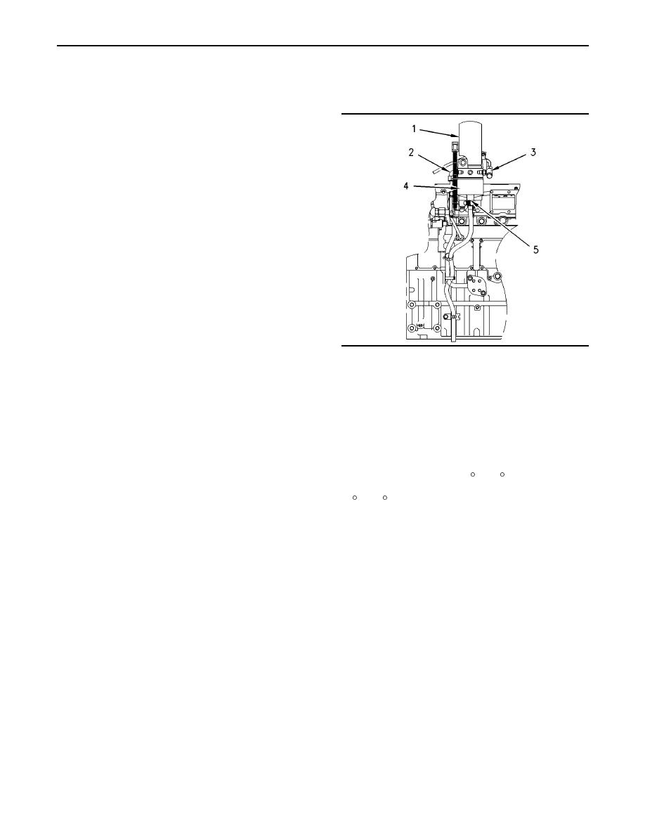
Illustration 22
rocker arm compartment under the valve cover.
(1)
Fuel filter
(2)
Fuel inlet
When the downward travel of the plunger stops,
(3)
Fuel outlet
(4)
Fuel heater and water separator
fuel flow also stops. While the check is still open,
(5)
Drain valve
the remaining fuel pressure pushes a small amount
of fuel out of the orifice holes. This causes a large
Some engines may have a combination of a fuel
pressure drop which lowers injection pressure
heater and a water separator. The fuel heater is
below Valve Closing Pressure (VCP). Spring tension
controlled by a thermostat that is located in the
on the check now reseats the check into the tip and
base of the unit. The thermostat is preset. When the
injection stops.
fuel temperature is below 4 C (40 F), the thermostat
will turn on the heater. When the fuel temperature is
When the check closes, injection stops. When
15 C (60 F), the thermostat will turn off the heater.
injection stops, the fill cycle starts. The area above
the intensifier piston cavity is open to atmospheric
Water that has been separated from the fuel can be
pressure through the upper poppet seat. Pressure
drained from the unit by lifting up on drain valve (5).
drops very rapidly in the cavity above the intensifier
piston to near zero. The return spring of the plunger
pushes up on the plunger and the intensifier piston.
As the plunger and the intensifier piston move
upward, oil is forced around the upper poppet seat.
After the oil is forced around the upper poppet seat,
the oil is forced out of a vent hole.
As the plunger rises, pressure in the plunger cavity
also drops to near zero. The fuel supply pressure is
450 kPa (65 psi). Fuel supply pressure unseats the
plunger fill check in order to fill the plunger cavity
with fuel. When the intensifier piston is pushed to
the top of the bore, the fill cycle ends. When the
fill cycle ends, the plunger cavity is full and the
inlet fill check ball is reseated. Pressure above the
intensifier piston and the poppet chamber is zero.
The fuel injection cycle is complete and the unit
injector is ready to begin again. The unit injector is
now back in the pre-injection cycle.
|
|
Privacy Statement - Press Release - Copyright Information. - Contact Us |
