 |
|||
|
|
|||
|
|
|||
| ||||||||||
|
|
 TM 9-2320-312-24-2
Specifications Section
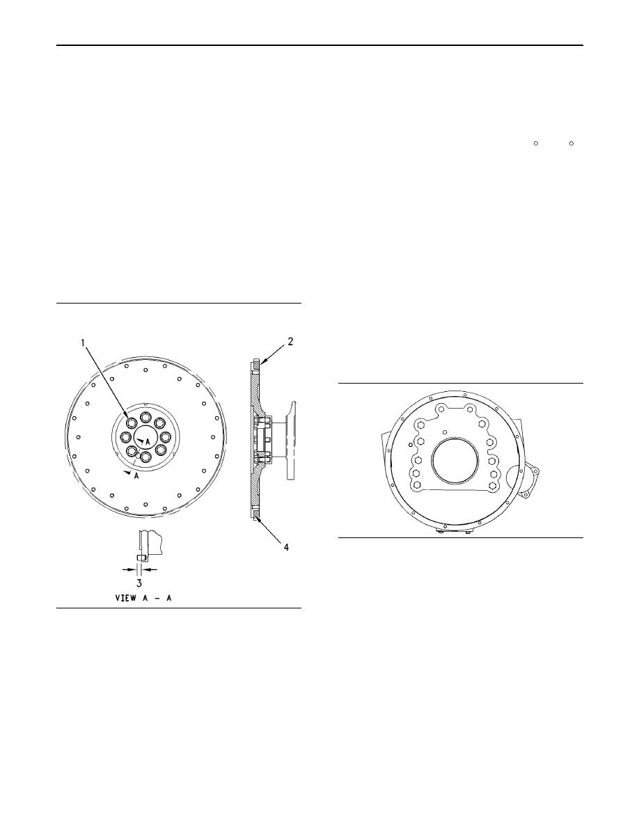
1. Install the flywheel ring gear. Face the "part
(7) Apply 9S-3263 Thread Lock Compound to the
number" on the ring gear (2) toward the engine
threads of the oil pump idler gear bolt. Tighten
block. The flywheel ring gear must be installed
the bolt to the following torque. ..... 70 15 Nm
against the shoulder (4). The flywheel ring gear
(50 11 lb ft)
can be heated for installation. Do not use a torch.
(8) Oil pump idler gear
Maximum temperature ................... 204 C (400 F)
Distance between the rear of the bearing face and
the rear of the gear face (C) ......... 0.75 0.25 mm
2. Press the spring pin (3) into the crankshaft before
(0.030 0.010 inch)
assembling the flywheel to the crankshaft. Check
the distance from the face of the crankshaft to
Diameter of new shaft (D) ........ 28.644 0.013 mm
the end of the pin (3).
(1.1277 0.0005 inch)
Distance ............. 11.0 1.0 mm (.43 .04 inch)
i00672569
3. Tighten the bolts (1) that hold the flywheel to the
Flywheel
crankshaft.
Tighten to the following torque. ..... 120 20 Nm
SMCS Code: 1156
(90 15 lb ft)
i00672686
Flywheel Housing
SMCS Code: 1157
g00293373
Illustration 49
Mounting face for the block
Note: Refer to Systems Operation, Testing and
Adjusting for the correct method of inspecting the
flywheel housing.
g00293319
Illustration 48
Note: Apply 1U-8846 Liquid Gasket to all of the
Note: Refer to System Operation, Testing and
sealing surfaces of the flywheel housing . The
Adjusting for the correct method of inspecting the
flywheel housing must be assembled and tightened
flywheel.
to the block within ten minutes.
(1) Bolt
(2) Ring gear
(3) Spring pin
(4) Shoulder
The following instructions should be used during
installation of the ring gear:
|
|
Privacy Statement - Press Release - Copyright Information. - Contact Us |