 |
|||
|
|
|||
|
|
|||
| ||||||||||
|
|
 TM 9-2320-312-24-2
Specifications Section
i01146333
Cylinder Head Valves
SMCS Code: 1105
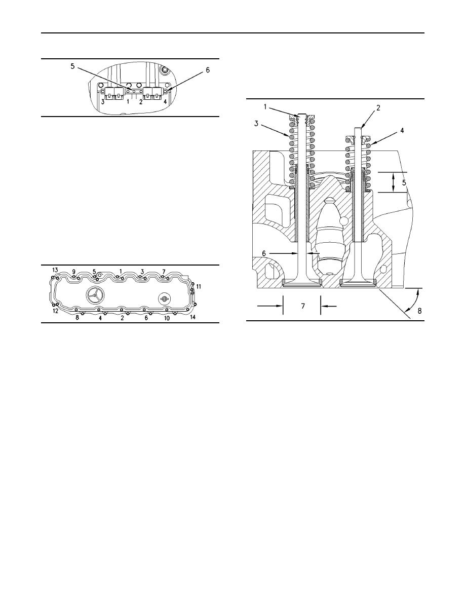
g00291847
Illustration 8
View A-A
(5) The lifter group must be installed with the oil
holes in the shaft, as shown.
(6) Apply 9S-3263 Thread Lock Compound.
Tighten the bolts that are shown above
in a numerical sequence to the following
torque. ........................ 13 3 Nm (10 2 lb ft)
i00666014
Valve Mechanism Cover
SMCS Code: 1107
g00291915
g00291835
Illustration 10
Illustration 9
Typical example
Note: The inlet and exhaust valve stems must be
coated with engine oil prior to installation in the
Tighten the bolts in a numerical sequence to the
cylinder head.
following torque. ................. 12 3 Nm (9 2 lb ft)
Note: The tips of the inlet and exhaust valves must
be coated with 8T-2998 Lubricant. The lubricant
must be applied after assembly of the retainer.
(1) Exhaust valve
(2) Inlet valve
(3) 137-6718 Spring for exhaust valve
Free length .................... 92.08 mm (3.625 inch)
Assembled length ......... 80.27 mm (3.160 inch)
Load at assembled length ............... 662 33 N
(148 7 lb)
Minimum operating length ................. 66.27 mm
(2.609 inch)
Load at minimum operating length .. 1445 58 N
(325 13 lb)
(4) 140-6188 Spring for inlet valve
Free length ........................ 67.5 mm (2.66 inch)
Assembled length ............. 60.4 mm (2.38 inch)
Load at assembled length ............... 303 18 N
(68 4 lb)
|
|
Privacy Statement - Press Release - Copyright Information. - Contact Us |