 |
|||
|
|
|||
|
|
|||
| ||||||||||
|
|
 TM 9-2320-312-24-2
Specifications Section
Specifications Section
i01147139
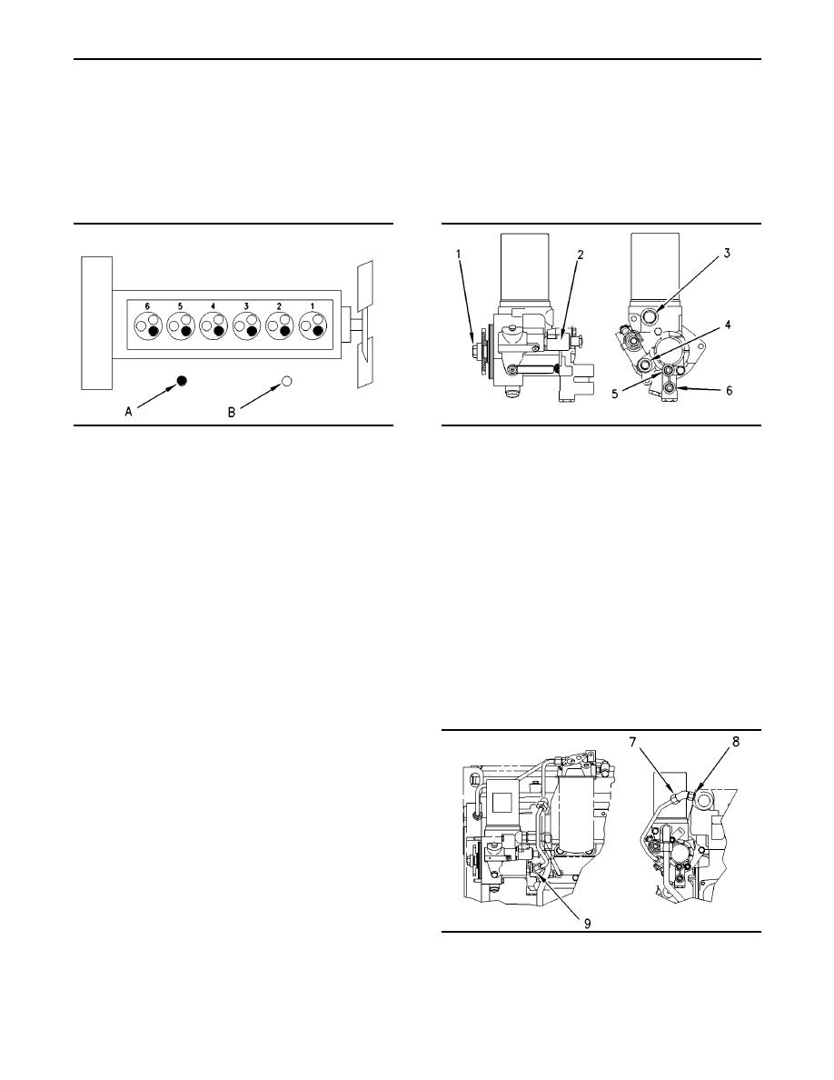
Fuel Transfer Pump
(Fuel Transfer Pump and High
i01146230
Pressure Oil Pump)
Engine Design
SMCS Code: 1256
SMCS Code: 1201
g00608597
g00290846
Illustration 2
Illustration 1
Cylinder And Valve Location
(1) Tighten the bolt to the following
(A) Exhaust valve.
torque. .................. 110 14 Nm (80 10 lb ft)
(B) Inlet valve.
(2) Injection actuation pressure control valve
Bore ............................................ 110 mm (4.3 inch)
(IAPCV)
Stroke .......................................... 127 mm (5.0 inch)
(3) Tighten the inlet of the oil pump to the following
torque. ........................ 26 3 Nm (19 2 lb ft)
Displacement .................................. 7.25 L (442 in 3 )
(4) Tighten the outlet of the oil pump to the following
Number of cylinders ............................................... 6
torque. ........................ 23 2 Nm (17 1 lb ft)
Cylinder arrangement ..................................... In-line
(5) Tighten the outlet of the fuel pump to the
following torque. ......... 18 2 Nm (13 1 lb ft)
Valves per cylinder ................................................. 3
(6) Tighten the inlet of the fuel pump to the following
In order to check the engine valve lash setting,
torque. ........................ 18 2 Nm (13 1 lb ft)
the engine must be cold and the engine must be
stopped. Engine valve lash settings
Inlet .................................. 0.38 mm (0.015 inch)
Exhaust ............................ 0.64 mm (0.025 inch)
Type of combustion .......................... Direct Injection
Firing Order ................................ 1 - 5 - 3 - 6 - 2 - 4
The crankshaft rotation is viewed from the
flywheel end of the engine. Crankshaft
rotation .......................................... counterclockwise
Note: The front end of the engine is opposite of
the flywheel end of the engine. The left side of the
g00617095
Illustration 3
engine and the right side of the engine are viewed
from the flywheel end of the engine. The number
(7) Tighten the nut on the tube assembly to the
one cylinder is the front cylinder.
following torque. ......... 37 4 Nm (27 3 lb ft)
|
|
Privacy Statement - Press Release - Copyright Information. - Contact Us |
