 |
|||
|
|
|||
|
|
|||
| ||||||||||
|
|
 TM 9-2320-312-24-1
REAR AXLE ASSEMBLY REPLACEMENT - CONTINUED
0145 00
REMOVAL
1.
Tag and disconnect two air lines from each brake chamber (WP 0031 00).
2.
Loosen all lug nuts on rear dual wheels.
3.
Raise rear of vehicle sufficiently to allow removal of rear dual wheels and achieve vertical clearance to remove rear axle
assembly (1).
4.
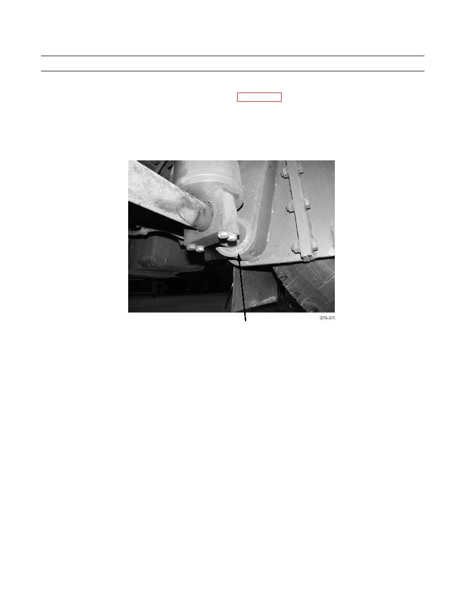
Place a jackstand or suitable cribbing under each side of frame, outboard of fifth wheel lift cylinder pivot tube.
SUPPORT EACH SIDE
OF VEHICLE WITH JACKSTAND
OR CRIBBING AT THIS LOCATION
5.
Remove rear dual wheels (TM 9-2320-312-10).
6.
Place a floor jack under rear axle differential. Raise jack sufficiently to support rear axle assembly (1) at differential.
7.
At each end of rear axle assembly (1), cut with torch and remove nut (7) and bolt (8) securing stabilizer bar (6) to frame
(9). Discard nuts and bolts.
8.
Cut with torch and remove nut (4) and bolt (5) securing stabilizer bar (6) to lower axle mounting cap (10). Discard nuts
and bolts.
9.
Cut with torch and remove eight nuts (2), bolts (3), and two lower axle mounting caps (10) securing rear axle assembly
(1) to frame (9). Discard nuts and bolts.
0145 00-2
|
|
Privacy Statement - Press Release - Copyright Information. - Contact Us |
