 |
|||
|
|
|||
|
Page Title:
PUMP-TO-TILT CYLINDER HOSES INSTALLATION - CONTINUED |
|
||
| ||||||||||
|
|
 TM 9-2320-312-24-1
CAB TILT HYDRAULIC HOSES AND FITTINGS REPLACEMENT - CONTINUED
0126 00
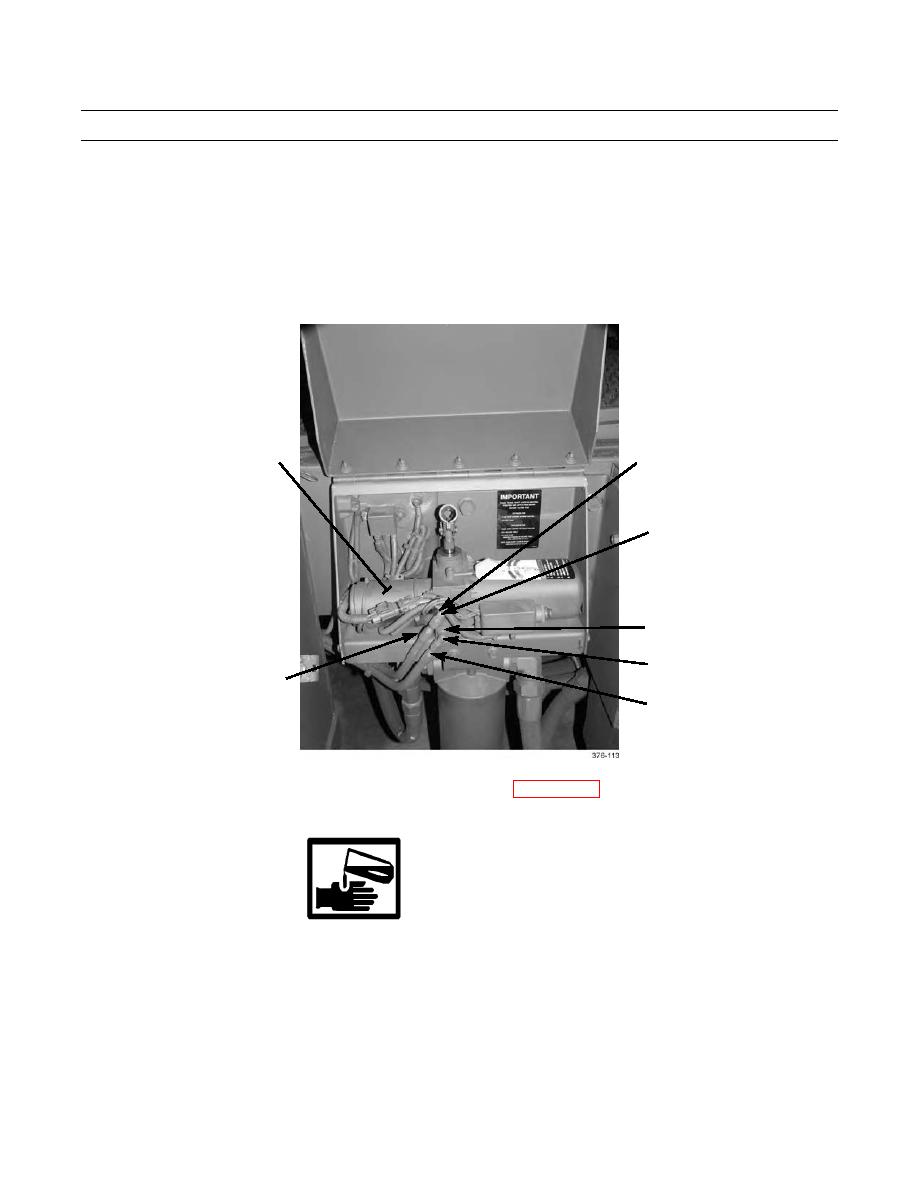
PUMP-TO-TILT CYLINDER HOSES INSTALLATION - CONTINUED
NOTE
Cab tilt latch hose is secured along with hoses (4 and 5), at clamp location closest to cab tilt cylinder.
3.
Route hoses (4 and 5) to pump (1). Secure hoses to welded studs (9) on frame rail with four clamps (10) and new lock-
nuts (8). Install new tiedown straps.
4.
If removed, install elbows (2 and 3) to pump (1).
5.
Connect hose (5) to elbow (2) at push port. Connect hose (4) to elbow (3) at pull port.
1
PUSH PORT
2
PULL PORT
3
5
4
6.
Place battery disconnect switch in ON position.
7.
Fill cab tilt pump reservoir as required, and bleed air from system (WP 0125 00).
CAB TILT LATCH HOSE REMOVAL
WARNING
When servicing this vehicle, performing maintenance, or disposing of materials such as engine coolant,
transmission fluid, lubricants, battery acids or batteries, consult your unit/local hazardous waste disposal
center or safety office for local regulatory guidance. If further information is needed, please contact The
Army Environmental Hotline at 1-800-872-3845.
CAUTION
Wipe area clean around all hydraulic connections prior to disconnecting. Cap or plug all openings after dis-
connecting. Contamination of hydraulic system could result in equipment failure.
0126 00-5
|
|
Privacy Statement - Press Release - Copyright Information. - Contact Us |
