 |
|||
|
|
|||
|
|
|||
| ||||||||||
|
|
 TM 9-2320-312-24-1
HEATER/AC UNIT BLOWER ASSEMBLY REPLACEMENT - CONTINUED
0055 01
INSTALLATION - CONTINUED
9.
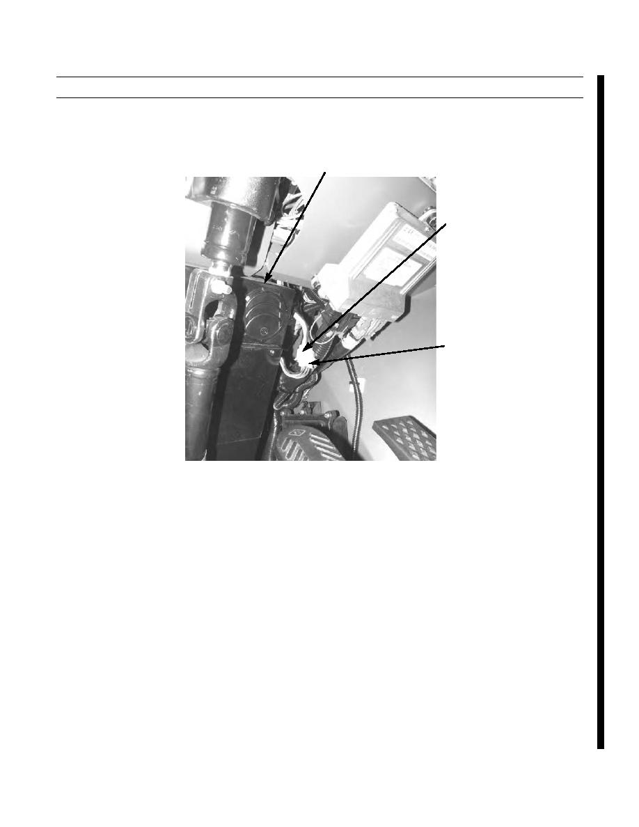
Connect heater/AC unit connector (3) to cab wiring harness connector (2).
1
2
3
376-340
10.
Place battery disconnect switch in ON position.
11.
Operate heater/AC fan switch on instrument panel to check operation of blower assembly (TM 9-2320-312-10).
END OF WORK PACKAGE
Change 1
|
|
Privacy Statement - Press Release - Copyright Information. - Contact Us |