 |
|||
|
|
|||
|
Page Title:
|
|
||
| ||||||||||
|
|
 TM 9-2320-312-24-1
STEERING COLUMN ASSEMBLY REPLACEMENT - CONTINUED
0035 00
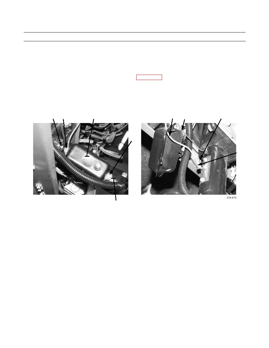
HORN REPAIR
1.
Ensure battery disconnect switch is in OFF position.
2.
Remove two screws (6), washers (7), and cover (24) from upper steering column (9).
3.
Remove screw (28) to disconnect wire (25) from contact brush (27). Remove wire from cover (24).
4.
Repair wires (25 and 26) or connectors in accordance with WP 0120 00 (Electrical General Maintenance Instructions).
5.
Feed wire (25) through opening in cover (24) and connect to contact brush (27) with screw (28).
6.
Install ground terminal (8) and cover (24) to upper steering column (9) with two washers (7) and screws (6).
7.
Place battery disconnect switch in ON position.
25
6,7
26
8
24
27
6,7
28
9
END OF WORK PACKAGE
0035 00-9/10 Blank
|
|
Privacy Statement - Press Release - Copyright Information. - Contact Us |
