|
| |
TM 9-2320-304-14&P
5-142.6
Organizational Maintenance Instructions (Cont)
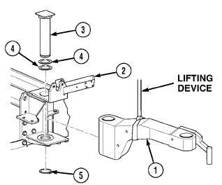
5-28.1 CONTAINER HANDLING UNIT (CHU) SLIDER ARM ASSEMBLY REPAIR (CONT).
e. Installation.
(1)
Apply grease to face of thrust washer,
seal, bore in arm assembly (1), and bores
and thrust face of rear roller bracket (2).
WARNING
Arm assembly weighs 240 lbs. (109 kg).
Attach suitable lifting device to prevent
possible injury to personnel.
(2)
Attach lifting device to arm
assembly (1).
CAUTION
Make sure not to damage bottom of
preformed packing during arm installation.
(3)
Soldier A and Soldier B position large
end of arm assembly (1) in rear roller
bracket (2).
WARNING
Use care when installing snap and retaining rings. Snap and retaining rings are under
spring tension and can act as projectiles when released and could cause severe eye injury.
NOTE
Install amount of shim(s) as noted prior to removal.
(4)
Apply grease to outer surface of pivot pin (3) and install pivot pin, shim(s) (4), and retaining
ring (5) in arm assembly (1) and rear roller bracket (2).
(5)
Remove lifting device from arm assembly (1).
f. Follow-on Maintenance.
(1)
Install horizontal roller (Para 4-48).
(2)
Install pin bracket assembly (Para 4-53.4).
(3)
Install slider/pivot assembly (Para 4-53.2).
(4)
Lubricate slider arm (Para 3-2).
(5)
Remove wheel chocks (TM 9-2320-279-10).
END OF TASK
5-29. OVERVIEW (HYDRAULIC SYSTEM).
The hydraulic pump is driven by the power takeoff (PTO) mounted on the transmission. There is a PTO switch
mounted in the cab to engage and disengage the PTO. The vehicle must be in neutral for proper operation of
the LHS.
Change 1
|