|
| |
TM 9-2320-304-14&P
5-79
Direct Support and General Support Maintenance (Cont)
5-15. GENERAL INSTALLATION INSTRUCTIONS.
a. Preparation. When unpacking items, remove all packing material, barrier paper, tape, plastic
bags, protective caps, and protective grease coatings. Handle and store removed components carefully.
CAUTION
Use sealing compound sparingly and only on male threads. Do not apply compound on first
two threads to avoid contamination of system from compound. Do not apply compound to
hose connections or fittings with preformed packings. Damage to equipment may result.
b. Sealing Compounds. Use sealing compounds as required in each maintenance task.
c. Torquing. Tighten bolts, screws, washers, hoses, and fittings as required in Appendix J or in each
maintenance task.
d. Identification Tags. Put hoses, tubes, lines, and electrical wiring in place by matching
identification tags and markings on equipment.
e. Hoses and Wiring. After installing hoses and wiring ensure that they do not contact moving part
or component edges. Secure in place, out of way with cable ties and cushion clips.
f. Hose and Fitting Tightening Procedure.
NOTE
Tighten hoses and fittings as required in
Appendix J or in each maintenance task.
If a torque wrench and crowsfoot are not
available or cannot be used, use the
following procedure.
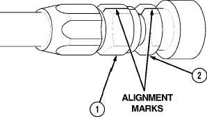
(1) Install hose nut (1) on fitting (2).
NOTE
When turning effort increases, hose nut
seat is in contact with adapter seat.
(2) Tighten hose nut (1) until seated on
fitting (2).
NOTE
Alinement marks allow the mechanic to
count the number of flats the hose nut has
rotated during tightening.
(3) Scribe alinement mark on hose nut (1)
and fitting (2).
(4) Tighten hose nut (1) until mark on hose
nut has rotated correct number of flats
(Refer to Table 5-3).
|

