|
| |
TM 9-2320-304-14&P
4-234.76
Organizational Maintenance Instructions (Cont)
4-58. HYDRAULIC HOSE REPLACEMENT.
Special Tools
None
This task covers:
a. Typical Hydraulic Coupling Removal
d. Typical Clip, Clamp, and Bracket Installation
b. Typical Hydraulic Coupling Installation
e. Hydraulic Lines
c. Typical Clip, Clamp, and Bracket Removal
f. Follow-on Maintenance
INITIAL SETUP
Personnel Required
MOS 63S, Heavy wheel vehicle mechanic
Equipment Condition
TM or Para
Condition Description
TM 9-2320-279-10 Engine OFF
TM 9-2320-279-20 Hydraulic reservoir
drained (only when
replacing reservoir lines)
References
None
Models
M1120
Test Equipment
None
Special Environmental Conditions
None
General Safety Instructions
None
Supplies
Tags, Identification, Item 19, Appendix F
Ties, Cable, Item 4, Appendix F
NOTE
·
This procedure only shows location of LHS hydraulic lines. Refer to
TM 9-2320-279-20 for vehicle hydraulic lines. It will never be necessary to remove
all hydraulic lines at once.
·
All hydraulic lines are connected with compression fittings. Some fittings will not
have preformed packings. Fitting from which hydraulic line is being removed or
installed can be an elbow, tee, or adapter on a valve or other hydraulic component or
hydraulic lines. All compression fittings are removed and installed the same way.
Elbow fitting is shown.
·
Tag and mark position of all hydraulic lines. Cut plastic cable ties as necessary.
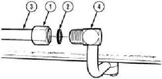
a. Typical Hydraulic Coupling Removal. Loosen
fitting (1). Remove preformed packing (2) and
hose (3) from elbow (4).
b. Typical Hydraulic Coupling
Installation. Install preformed packing (2) and
connect hose (3) on elbow (4) with fitting (1).
Change 1
|

