|
| |
TM 9-2320-304-14&P
4-163
Organizational Maintenance Instructions (Cont)
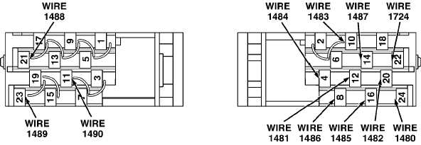
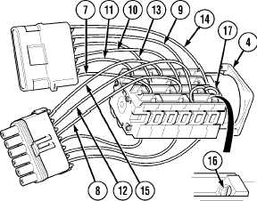
(3) Install wires 1724 (7), 1487 (8), 1483 (9),
1481 (10), 1480 (11), 1486 (12),
1482 (13), 1484 (14), and 1485 (15) in
hydraulic selector switch (4) with nine
screws (16).
(4) Install two jumperwires (17) in
hydraulic selector switch (4) with two
screws (16).
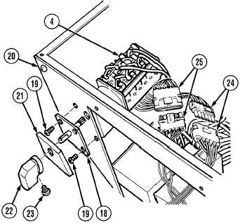
(5) Install hydraulic selector switch (4),
hydraulic selector switch front
mounting plate (18), and four
screws (19) on heater compartment (20).
NOTE
Hydraulic selector switch face plate snaps
in place.
(6) Install hydraulic selector switch face
plate (21) on hydraulic selector switch
front mounting plate (18).
(7) Install knob (22) on hydraulic selector
switch front mounting plate (18) with
screw (23).
(8) Connect MC94 connector (24).
(9) Connect MC93 connector (25).
|


