|
| |
TM 9-2320-304-14&P
2-82.103
Operating Instructions (Cont)
NOTE
·
There are two front lift adapter lower container locks and rear sliders. Right side
shown.
·
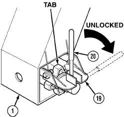
Make sure front lift adapter lower container lock handle is positioned in slot on
handle lock plate.
·
Make sure tab on handnut faces up.
(18)
Raise handle lock plate (19) and rotate lower container lock handle (20) toward center of front
lift adapter (1) to unlocked position.
(19)
Release handle lock plate (19) on front lift adapter (1).
(20)
Repeat steps (18) and (19) for left side.
CAUTION
Make sure sliders are clear of debris and surfaces are properly greased or damage to
equipment may result.
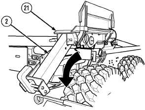
NOTE
There are two rear sliders and container locks. Right side shown.
(21)
Rotate slider (21) so rear of slider faces down.
(22)
Make sure rear container lock (2) is in ready mode or down position (Para 2-10.1).
(23)
Repeat steps (21) and (22) for left side.
(24)
Start engine (TM 9-2320-279-10).
Change 1
|