|
| |
TM 9-2320-304-14&P
5-261
Direct Support and General Support Maintenance (Cont)
NOTE
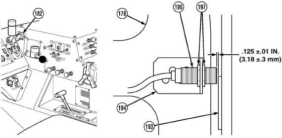
Proximity switch is properly positioned when two threads extend past edge of nut.
(192) Position CHU main frame up proximity switch (196) on proximity switch mount (194).
(193) Connect batteries (TM 9-2320-279-20).
(194) Start engine (TM 9-2320-279-10).
CAUTION
Engine speed must be at idle before using hydraulic selector switch, or damage to
equipment may result.
(195) Set hydraulic selector switch (182) to MAN M.F. position and raise main frame (178) until
approximately half of proximity switch (196) is covered by sensing plate (193).
(196) Shut OFF engine (TM 9-2320-279-10).
(197) Using feeler gage, adjust clearance between CHU proximity switch (196) and sensing plate (193)
to 0.125 ±0.01 in. (3.18 ±0.3 mm) and tighten nuts (197).
(198) Disconnect batteries (TM 9-2320-279-20).
Change 1
|

