 |
|||
|
|
|||
|
Page Title:
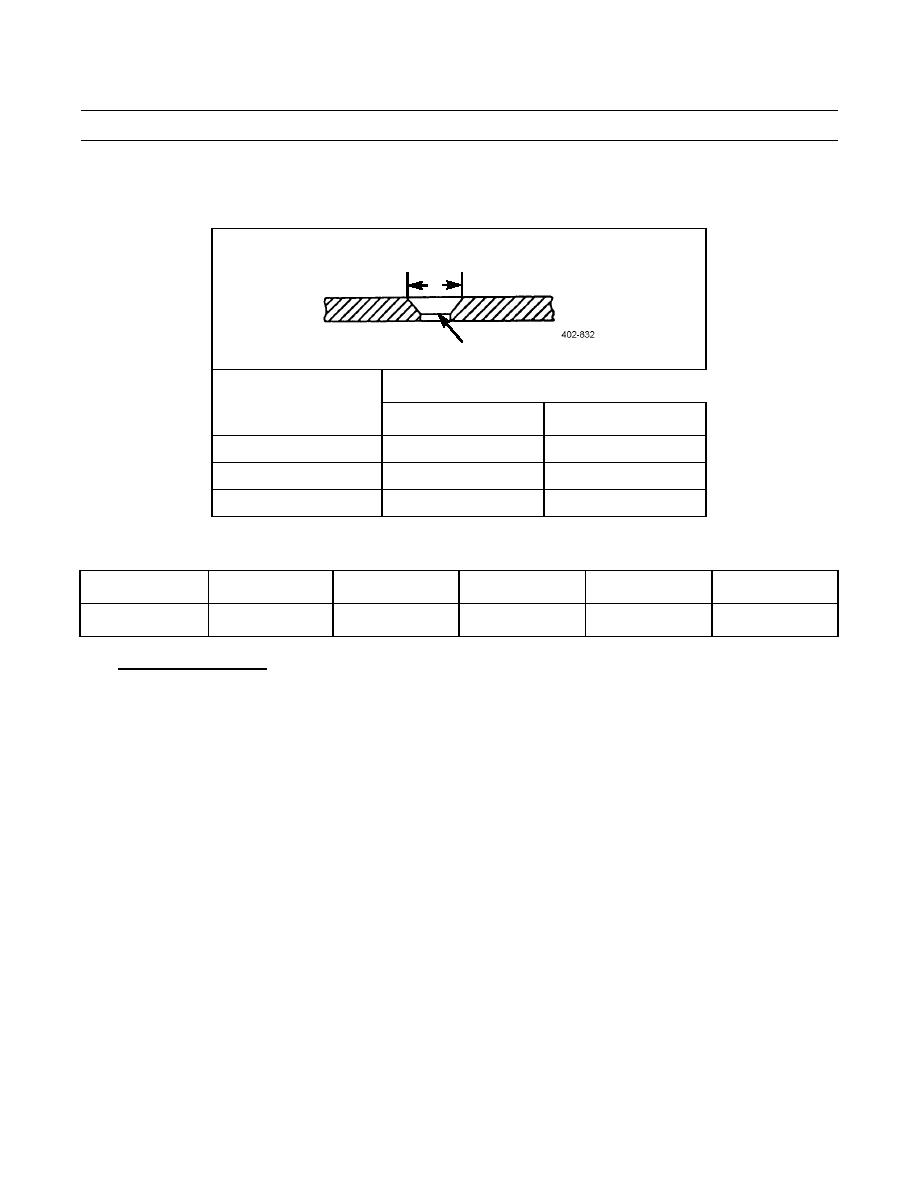
Table 3. Countersinking Dimensions for 100-Degree Countersunk Blind Rivets. |
|
||
| ||||||||||
|
|
 TM 9-2320-303-24-2
CAB BODY REPAIR - CONTINUED
0289 00
RIVET REPLACEMENT - CONTINUED
Table 3. Countersinking Dimensions for 100-Degree Countersunk Blind Rivets.
Countersinking Dimensions (100)
C
01 OR MIN.
Rivet
C (in)
Diameter (in)
Minimum
Maximum
1/8
0.222
0.228
5/32
0.283
0.289
3/16
0.350
0.356
Table 4. Minimum Sheet Gage for 100-Degree Machine Countersink.
3/32
1/8
5/32
3/16
1/4
Rivet Size (in)
0.040
0.050
0.064
0.072
0.072
Gage (in)
Solid Rivet Installation.
6.
NOTE
When replacing rivets during repair, use same rivet size and type, if possible. If hole has been damaged, it
will be necessary to drill hole oversize and use next larger rivet or oversize blind rivet.
a.
After drilling and prior to driving rivets, parts to be joined must be secured to prevent slipping during riveting. C-
clamps may be used, or any of several varieties of skin fasteners may be inserted in previously drilled holes.
CAUTION
When riveting thin gage materials, be careful handling rivet tools to avoid damaging material.
b.
Solid rivets are available in various lengths. Correct length rivet must be chosen so bucked head is not too small or
too large to form tight fit. Use Table 5 to determine proper rivet length.
c.
Three common methods of driving or setting rivets are: hand, squeeze, and pneumatic gun. All three methods use
principle of upsetting or heading rivet shank against bucking bar.
0289 00-6
|
|
Privacy Statement - Press Release - Copyright Information. - Contact Us |
