 |
|||
|
|
|||
|
|
|||
| ||||||||||
|
|
 TM 9-2320-303-24-1
SLACK ADJUSTER ADJUSTMENT - CONTINUED
0128 00
ADJUSTMENT - CONTINUED
CAUTION
The clevis MUST be installed in the correct position on the push rod or the slack adjuster will not adjust the
brake correctly resulting in premature wear of brakes.
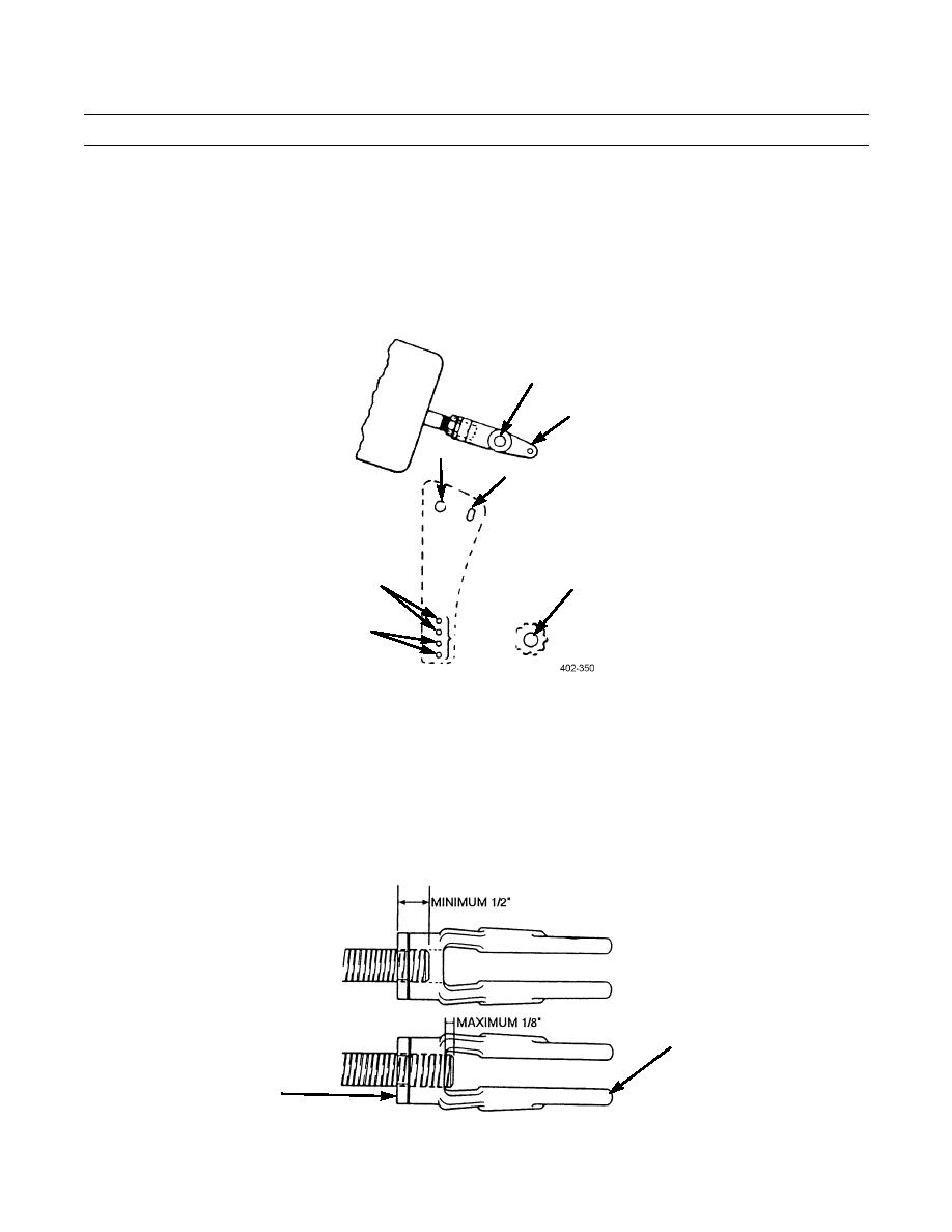
2.
Put the large clevis pin (3) through the large holes (9) in the template and the clevis (4).
3.
Select the hole (8) in the template that matches the length of the slack adjuster. Hold that hole on the center of the cam-
shaft or powershaft (7).
3
4
9
6
8
7
8
4.
Look through slot (6) in the template. The small hole (8) in the clevis MUST be completely visible.
5.
If necessary, adjust the position of the clevis (4) on the push rod until the small hole (5) in the clevis is completely visi-
ble through the slot (6) in the template.
6.
Tighten the jam nut (10) against the clevis (4) to hold the clevis in the correct position. For the -20 threads, tighten the
jam nut to a torque of 20-30 lb-ft (27-41 Nm). For 5/8-18 threads, tighten the jam nut to a torque of 25-50 lb-ft (34-68
Nm).
7.
There must be at least inch (12.7 mm) of thread engagement between the clevis and the push rod. The push rod must
not extend through the clevis more than 1/8 inch (3.18 mm).
8.
If adjustment cannot be obtained, install new air brake chamber.
4
10
402-351
0128 00-2
|
|
Privacy Statement - Press Release - Copyright Information. - Contact Us |
