 |
|||
|
|
|||
|
|
|||
| ||||||||||
|
|
 TM 9-2320-303-24-1
FRONT BLACKOUT MARKER LIGHT REPLACEMENT - CONTINUED
0101 00
REMOVAL - CONTINUED
10,11,12
13
14,15
9
16
8
10,11,12
INSTALLATION
1.
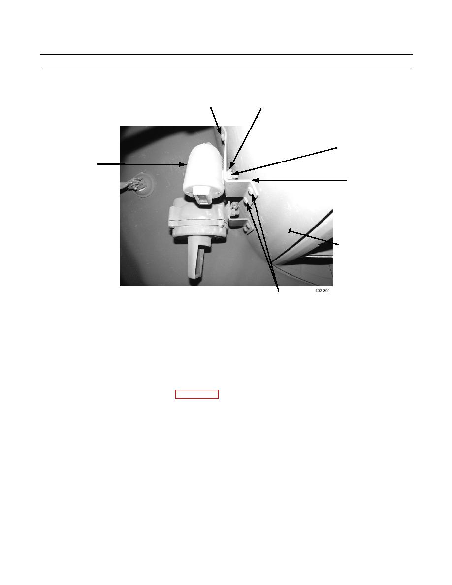
If removed, install mounting bracket (16) to fender (8) with three screws (12), washers (11), and new locknuts (10).
NOTE
Ensure that wire loom is installed over wires before wires are fed through fender.
2.
Feed blackout marker and drive light wires through grommet (1) and fender (8). Seat grommet in fender.
3.
Install blackout marker light (9) and ground wire (13) to mounting bracket (16) with new lockwasher (15) and nut (14).
4.
Install connectors (2, 4, and 5) on wires (WP 0098 00).
5.
Connect blackout drive light (2-wire) connector (5) to wiring harness connector (6).
6.
Connect blackout marker light (single-wire) connector (4) to wiring harness connector (7).
7.
Connect blackout marker light connector (2) to wiring harness connector (3).
8.
If installing left-front blackout marker light, install wire looms around wires and secure wire looms with electrical tape.
END OF WORK PACKAGE
0101 00-3/(0101 00-4 blank)
|
|
Privacy Statement - Press Release - Copyright Information. - Contact Us |