 |
|||
|
|
|||
|
Page Title:
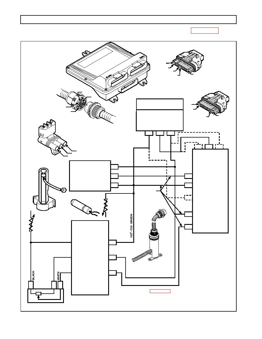
Figure 521. Code 64 Schematic Drawing |
|
||
| ||||||||||
|
|
 WTEC III ELECTRONIC CONTROLS TROUBLESHOOTING MANUAL
"T" CONNECTOR
(
BLUE)
ECU
T16
T32
T26
T1
T25
UE
BL
"S" CONNECTOR
(
N
BLACK)
UE
BL
Y
TO RETARDER
S16
CONTROL DEVICES
A
S32
D
RTDRRMODULATION
S1
S3
R EQUEST
ESISTANCE
M
FRANSMISSION
T
ODULE
EEDTHROUGH
H
C ARNESS
124*S3 PINK
A
B
C
ONNECTOR
164T11 YELLOW
164S20
135BT25
T11
S20
S3
GREEN
A
TPS OR
R
RTDR
B
C
MR
MOD.
C
135-S19
SIGNAL
ONNECTOR
124*T9
PINK
C
THROTTLE
P
156T10
BLUE
S SITION
O
T10 THROTTLE SIGNAL
B
ENSOR
GREEN
135*T25
TPS LO
A
T25 (ANALOG GROUND)
SEE NOTE
135*T25
S19
RETARDER
ECU
S EMP
ENSOR
SENSOR POWER
T9
SUMP
T
S EMP
T26 OIL LEVEL
ENSOR
SENSOR INPUT
TRANSMISSION
BLACK
SUMP TEMP SENSOR
N
AND OIL LEVEL
SENSOR GROUND
RED
OIL LEVEL
D
SENSOR POWER
OIL LEVEL
Y
124*T9 PINK
SENSOR SIGNAL
165T26 BLUE
D
B
A
See Appendix D For Detailed Terminal Location.
RED
a
*Wire designation may include a letter suffix which indicates
BLUE
A splice to the same number wire. See wiring schematic in
ppendix J for more detail on splice letter designations.
NOTE: These wires may pass through a bulkhead connector.
V03365
0021 00114
|
|
Privacy Statement - Press Release - Copyright Information. - Contact Us |