 |
|||
|
|
|||
|
Page Title:
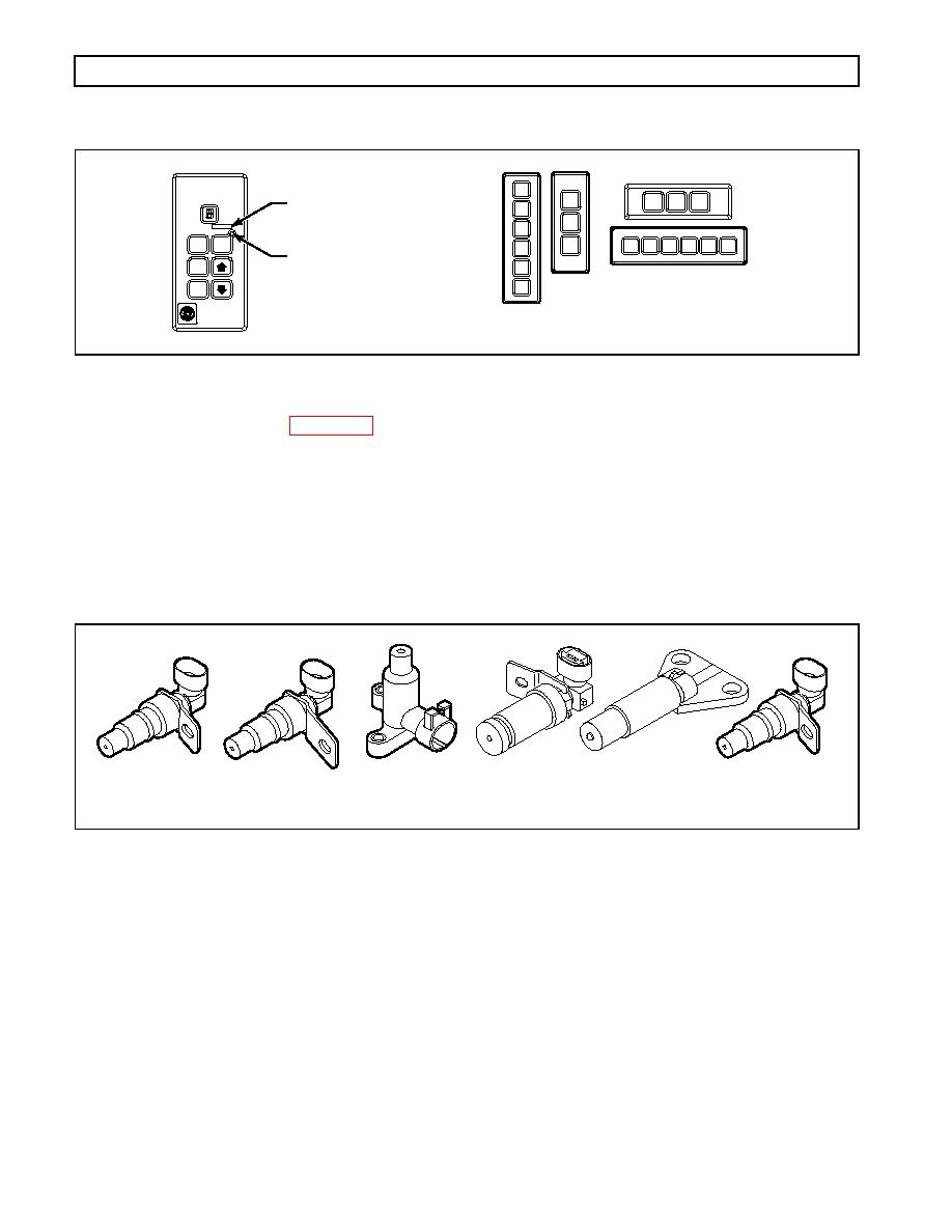
Figure 14. Pushbutton Shift Selectors |
|
||
| ||||||||||
|
|
 WTEC III ELECTRONIC CONTROLS TROUBLESHOOTING MANUAL
GENERAL DESCRIPTION
1
D
D N R
MODE ID
2
N
3
R
R
1
2
3
DNR
MODE
D
MODE INDICATOR (LED)
N
N
R
D
PUSHBUTTON
S
STRIP PUSHBUTTON
S
ELECTOR
HIFT SELECTORS
V03356
Three speed sensors -- engine speed, turbine speed, and output speed -- provide information to the ECU. The
engine speed signal is generated by ribs on the shell of the torque converter pump. The turbine speed signal is
generated by the rotating-clutch housing spline contours. The output speed signal is generated by a toothed
member attached to the output shaft (except for the MD 3070, where the toothed member is the transfer case idler
gear). The speed ratios between the various speed sensors allow the ECU to determine if the transmission is in the
selected range. Speed sensor information is also used to control the timing of clutch apply pressures, resulting in
the smoothest shifts possible. Hydraulic problems are detected by comparing the speed sensor information for the
current range to that range's speed sensor information stored in the ECU memory.
ENGINE
HD/B 500
MD/B 300/B 400
MD/B 300/B 400
MD 3070 PT
OUTPUT
(EXTERNAL)
TURBINE
TURBINE
RETARDER OUTPUT
OUTPUT
(EXTERNAL)
(EXTERNAL)
(INTERNAL)
(EXTERNAL)
(INTERNAL)
V03470
|
|
Privacy Statement - Press Release - Copyright Information. - Contact Us |
