 |
|||
|
|
|||
|
|
|||
| ||||||||||
|
|
 TM 9-2320-302-20-2
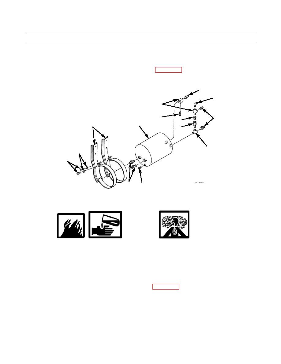
AIR SUPPLY TANK AND FITTINGS REPLACEMENT (M915A3, M916A3) - CONTINUED
0186 00
REMOVAL - CONTINUED
6.
Remove five connectors (18), safety valve (16), elbow (19), two tees (17), bushing (20), check valve (21), tee (22), and
drain valve (23) (M915A3 Old Model) from air supply tank (11).
For M915A3 New Model and M916A3, remove auto drain valve (WP 0171 00).
7.
8.
Remove two screws (13), washers (14), and mounting brackets (15) from air supply tank (11).
18
19
17
18
16
20
11
15
21
22
14
13
18
23
INSTALLATION
1.
Install two mounting brackets (15), washers (14), and screws (13) on air supply tank (11).
WARNING
Adhesives and sealing compounds can burn easily, can give off harmful vapors, and are harm-
ful to skin and clothing. To avoid injury or death, keep away from open fire and use in a well-
ventilated area. If adhesives or sealing compound gets on skin or clothing, wash immediately
with soap and water.
Ensure all air lines and fittings are clear of debris and excess pipe sealing compound does not
enter air lines or fittings. Failure to follow this warning could result in injury to personnel or
damage to equipment.
For M915A3 New Model and M916A3, install auto drain valve (WP 0171 00).
2.
3.
Coat pipe threads of drain valve (23) (M915A3 Old Model), tee (22), check valve (21), bushing (20), two tees (17),
elbow (19), safety valve (16), and five connectors (18) with pipe sealing compound.
4.
Install drain valve (23), tee (22), check valve (21), bushing (20), two tees (17), elbow (19), safety valve (16), and five
connectors (18) in air supply tank (11).
5.
Install air supply tank (11), four washers (5), screws (6), washers (12) and new locknuts (1).
6.
Connect cable (9) and install new cotter pin (10).
0186 00-2
|
|
Privacy Statement - Press Release - Copyright Information. - Contact Us |
