 |
|||
|
|
|||
|
Page Title:
FRONT SLACK ADJUSTER INSTALLATION - CONTINUED |
|
||
| ||||||||||
|
|
 TM 9-2320-302-20-2
SLACK ADJUSTER AND S-CAM REPLACEMENT- CONTINUED
0180 00
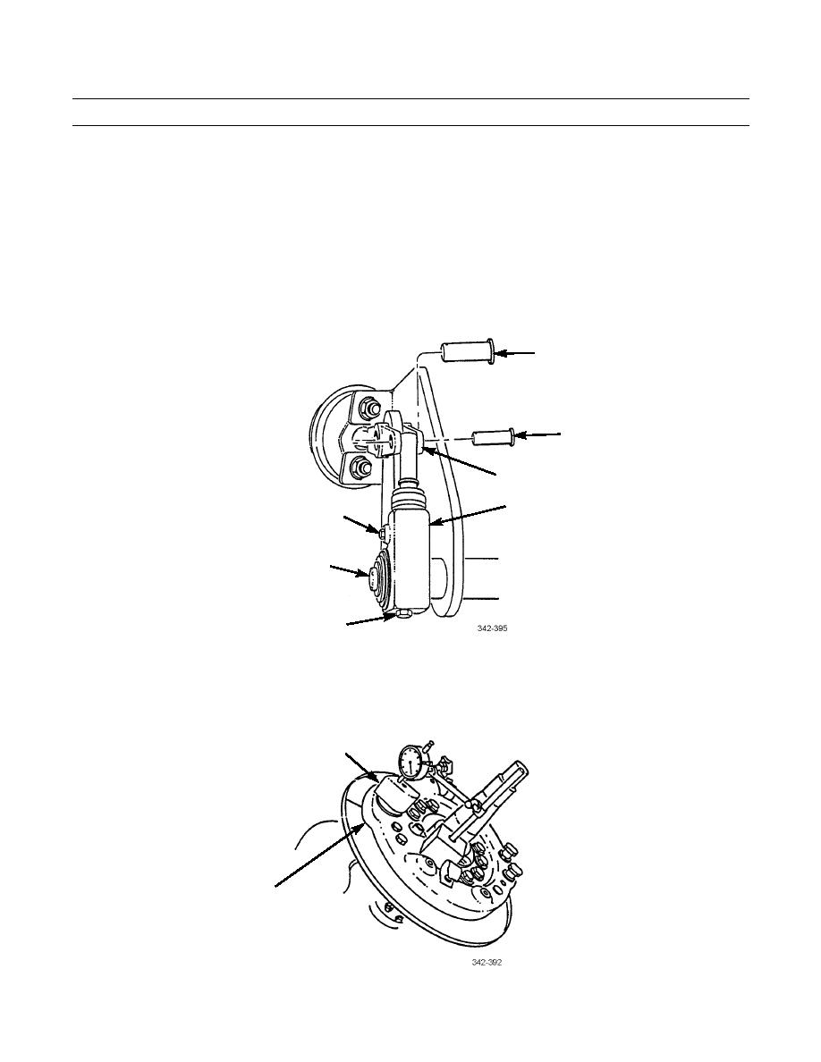
FRONT SLACK ADJUSTER INSTALLATION - CONTINUED
5.
Remove screw (25), spring (26), and pawl (27) from slack adjuster (11).
6.
Rotate adjusting screw (28) to align slack adjuster (11) with front brake chamber clevis (4).
7.
Hold s-cam (6) in position and rotate adjusting screw (28) to align slack adjuster (11) with clevis (4).
8.
Install clevis pins (2 and 3).
9.
Install pawl (27), spring (26), and screw (25) on slack adjuster (11). Tighten screw to 15-20 lb-ft (20-27 Nm).
10.
Ensure that s-cam (6) is against brake spider (29).
2
3
4
11
25,26,27
6
28
11.
Attach magnetic base of dial indicator to brake spider (29) with indicator point on end surface of s-cam (6). Set dial indi-
cator to zero.
12.
Push s-cam (6) outward to end of travel and check new reading on dial indicator. If reading is more than 0.06 in (1.5
mm), perform Removal steps 2 through 4 and Installation steps 1 through 12.
6
29
0180 00-4
|
|
Privacy Statement - Press Release - Copyright Information. - Contact Us |
