 |
|||
|
|
|||
|
|
|||
| ||||||||||
|
|
 TM 9-2320-302-20-2
FRONT BLACKOUT MARKER LIGHT REPLACEMENT - CONTINUED
0099 00
REMOVAL
NOTE
Remove tiedown straps as required and discard.
Tag connectors to ensure correct installation.
1.
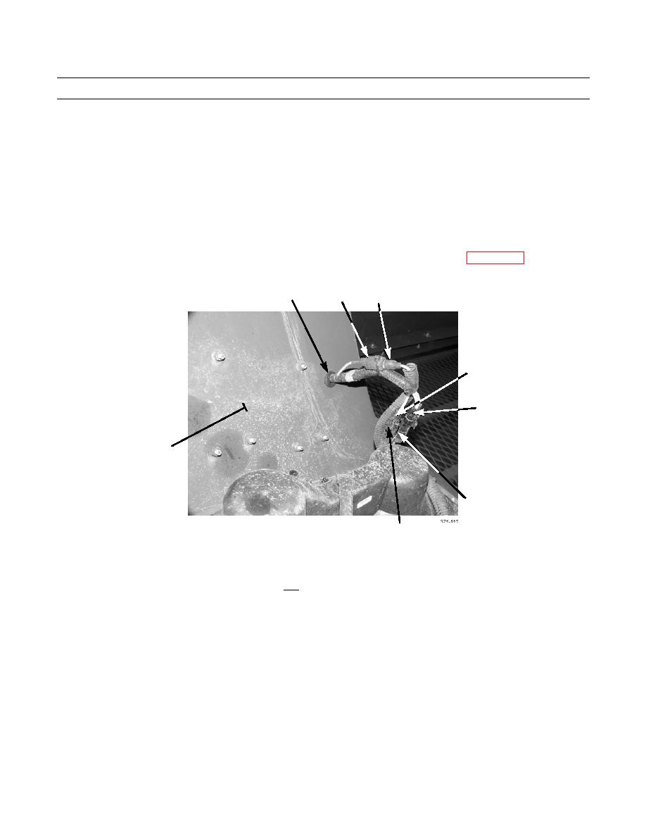
Disconnect blackout marker light connector (2) from wiring harness connector (3).
2.
Disconnect blackout marker light (single-wire) connector (4) from wiring harness connector (7).
3.
Disconnect blackout drive light (2-wire) connector (5) from wiring harness connector (6).
4.
If removing left-front blackout marker light, remove electrical tape and wire looms. Separate blackout marker light
wires from blackout drive light wires. Remove connectors (2, 4, and 5) from ends of wires (WP 0151 00).
1
3
2
4
5
8
6
7
5.
Remove nut (14), lockwasher (15), ground wire (13), and blackout marker light (9) from mounting bracket (16). Discard
lockwasher.
6.
Remove grommet (1) and pull blackout marker and drive light wires through fender (8) while removing blackout marker
light (9).
7.
If damaged, remove three locknuts (10) washers (11), screws (12), and mounting bracket (16) from fender (8). Discard
locknuts.
0099 00-2
|
|
Privacy Statement - Press Release - Copyright Information. - Contact Us |
