 |
|||
|
|
|||
|
Page Title:
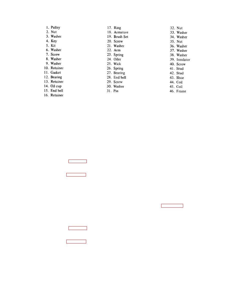
Figure 4-18. Generator (Sheet 2 of 2) |
|
||
| ||||||||||
|
|
 TM 55-1740-200-14
Figure 4-18. Generator (Sheet 2 of 2)
b. Remove screw (9) and toggle switch (10). Remove
b. Remove screw (2) and lift assembled lamp from
screw (12) and cap (11 ). Remove two screws (19) and
housing (10). Loosen screw and remove cable (9) from
strap (18). Remove screw (15), switch (13) and gear (14)
a s s e m b l e d lamp.
from housing (20).
c. Remove three clips (3) and remove lamp (5) from
c. Remove screw (22) and ornament (21). Remove
ring (1). Remove screw and ground bar (4) from lamp
screw (24) and lift ring and lamp from shell (33). Remove
(5). Remove wire assembly (9) from housing (1 O).
four clips (25) and remove ring (23) from lamp (26).
4-274. HEADLIGHT.
d. Remove nut (28), washer (29) and shell (33).
Remove bushing (30), spring (31) and washer (32) from
4-275. REMOVAL. Refer to Chapter 3, Section VI for
post assembly (27).
r e m o v a l instructions.
e. Remove pin (36), setscrew (37) and post assembly
(27) from housing (39). Remove screw (35) and plug
4-276. DISASSEMBLY. See figure 4-24 and dis-
(34); slide tube and gear (38) from housing (39). Remove
assemble the headlight as follows:
screws (40 and 41) and slide tubes (42 and 43) from
housing (39).
a. Remove nut (1) and three washers (2, 3 and 4).
Remove screw (5) and rim (6).
4-280. lNSTRUMENT PANEL.
b. Remove three screws (8) and retainer (7). Remove
4-281. REMOVAL. See figure 4-26 and remove the
lamp (9) and unplug wiring assembly (10). Remove wiring
instrument panel as follows:
assembly (10) from body (11 ).
a. Remove shaft assembly (13) from speedometer.
4-277. SPOTLIGHT.
Disengage sensor unit from the engine. Disconnect choke
cable from the carburetor. Remove two screws (1) and
4-278. REMOVAL. Refer to Chapter 3, Section VI for
four washers (2). Remove two screws (3), four washers
removal instructions.
(4) and two nuts (5).
4-279. DISASSEMBLY. See figure 4-25 and dis-
NOTE
assemble the spotlight as follows:
Sensor unit is a permanent part of gage cluster
a. Remove screw (2), lower handle (1) and upper
(17). Extreme care should be used when
handle (3). Remove nut (4), washer (5), washer (6),
removing sensor wire through the firewall.
adapter (7) and pinion (8).
4-53
|
|
Privacy Statement - Press Release - Copyright Information. - Contact Us |
