 |
|||
|
|
|||
|
|
|||
| ||||||||||
|
|
 TM 55-1740-200-14
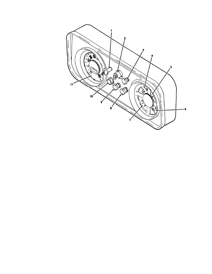
1.
CHOKE
2.
IGNITION STARTER SWITCH
3.
WINDSHIELD WIPER SWITCH
4.
TEMPERATURE GAGE
FUEL GAGE
5.
6.
OIL PRESSURE GAGE
7.
FLOODLIGHT SWITCH
8.
HEADLIGHT SWITCH
9.
HEATER SWITCH
10.
11.
SPEEDOMETER
AV
008858
2-34. OIL PRESSURE GAGE. The oil pressure gage (6)
b. Check radiator for proper coolant level and remove
any outside radiator obstructions.
indicates engine oil pressure. During normal driving
operations, the gage should register 30 to 55 pound
c. Conduct visual checks for water and oil leaks.
pressure.
d. Check for proper engine oil and hydraulic oil levels.
2-35. AMMETER. The ammeter (7) indicates the rate of
battery charge or discharge. Ammeter should indicate
e. Turn ignition switch clockwise to first position and
charge or neutral during normal driving operation.
check fuel gage for sufficient fuel.
2-36. SPEEDOMETER. The speedometer (11) indicates
f. Check all lights for proper operation,
forward tractor speed. An odometer registers miles
traveled. The high beam indicator light is located at the
top of the speedometer face.
2-40. START ENGINE.
2-38. PRESTART CHECKS.
2-41. To start the tractor engine proceed as follows:
a. Set parking brake by pulling up and back on
2-39. Before starting the tractor engine, conduct the
parking brake lever.
following checks:
b. Place transmission in neutral position.
a. Check the tires for proper inflation of 20 psi.
|
|
Privacy Statement - Press Release - Copyright Information. - Contact Us |
