 |
|||
|
|
|||
|
Page Title:
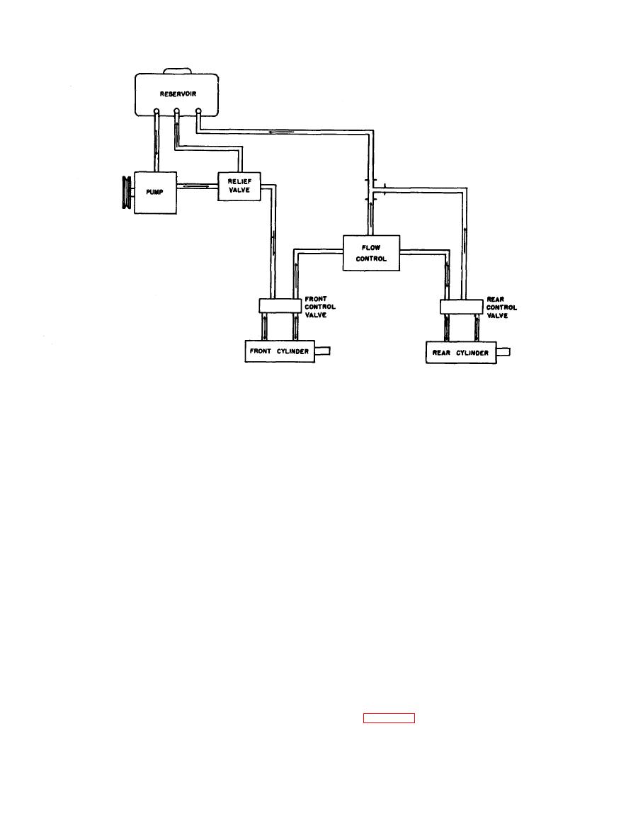
Figure 1-3. Tractor hydraulic steering flow diagram |
|
||
| ||||||||||
|
|
 TM 55-1740-200-14
AV
008852
131. IGNITION COIL. The ignition coil transforms
1 27. STARTING MOTOR. The starting motor is of the
battery voltage into high voltage for use by the spark
conventional four pole, four brush type and is securely
plugs.
bolted to the hydraulic transmission adapter plate.
128. GENERATOR, The large capacity, aircooled,
132. SPARK PLUGS. The six spark plugs are installed
shunt-type generator with automatic cutout, current and
on top of the cylinder head and are used to provide a
voltage regulator keeps the battery charged and maintains
high voltage spark to ignite the fuel and air mixture in
proper voltage under normal operating conditions.
the cylinder.
129. GENERATOR REGULATOR. The generator
regulator is mounted on the fire wall and reduces the
1 33. FUEL SYSTEM.
generator output when the maximum is not needed, thus
preventing high voltage and an overcharged battery.
1 34. The fuel supply is contained in a 20 gallon fuel
130. DISTRIBUTOR. The distributor is mounted on
tank (7, figure 1-2) which provides sufficient fuel for
the left side of the crankcase. Distributors on all tractors
eight hours operation. The fuel tank is mounted under
contain one set of contact points and are driven by a gear
the right, center section of the tractor.
on the camshaft.
.
|
|
Privacy Statement - Press Release - Copyright Information. - Contact Us |
