
TM 5-3815-221-14&P
The function of the drums during backhoe operation are
GENERAL INFORMATION
tabulated below. The numbers in the column "controls"
correspond to the items in Figure 2-1 of TM 5-3810-303-
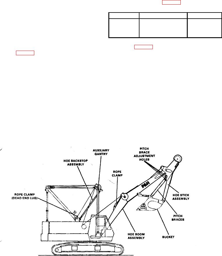
Figure 1 illustrates the backhoe attachment for the Model
14.
5060 Crane. This manual is confined to lubrication,
installation and removal, adjustments, and general
Drum
Function
Controls
information concerning operation and maintenance of the
Left
Dipper Stick
5, 6, 23, 25
backhoe attachment. It will also contain repair parts
Right
Backhoe Boom
4, 8, 24, 26
information
Boom Hoist
Backhoe Boom Line
11
BACKHOE WORKING RANGES
During backhoe operation install the planetary lowering
lockouts(see Figure 2-4, Item48 of TM5-3810-303-14).
The working ranges and other pertinent specifications
are tabulated in Figure 2
INSTALLING BACKHOEATTACHMENT
OPERATION
GENERAL
Positioning the Crane. Position the crane so that most of
The Truck Crane may be converted to backhoe
the work will be over the front or rear of the crawler.
operation by removing the crane boom and installing the
Dumping or unloading should be done over the sides of
backhoe front end attachment. The components
the crawler, if possible. Set the propel brakes. See Crane
necessary for the equipment conversion are: backhoe
Operator's Manual.
boom, backhoe bucket, auxiliary gantry mast, auxiliary
gantry backstop assembly, digging cable, and boom
Operating Cycle. The backhoe operating cycle consists
hoist cable.
of four steps; filling the dipper, hoisting, swinging, and
dumping. During backhoe operation, tension must be
maintained in both the left and the right drum lines at all
times, since they are interdependent. Start the crane
engine and operate the backhoe as given in the next
steps
Figure 1. Backhoe Assembly
1