 |
|||
|
|
|||
|
Page Title:
BRAKES AND AIR SYSTEM-continued |
|
||
| ||||||||||
|
|
 TM 5-2420-224-34
Table 2-1. Troubleshooting (Cont)
Malfunction
Test or Inspection
Corrective Action
BRAKES AND AIR SYSTEM (CONT)
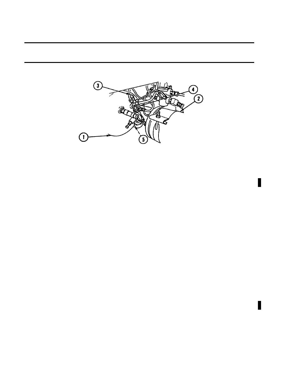
a. Relieve air pressure (TM 5-2420-224-20) completely from air tanks (1 and 2).
b. Attach 0-200 psi (0-14 bar) pressure gage to test connection (3).
NOTE
When fluid regulating valve reaches cut-out pressure, there will be an audible "pop". Inspect
all air supply lines.
c.
Start and run engine at idle until fluid regulating valve reaches cut-out pressure.
d. Compare pressure readings between 0-200 psi (0-14 bar) pressure gage and dual
brake gage. Both readings must be the same.
If pressure on both gages is zero, go to step e.
If pressure on both gages is the same, but less than 106 psi (7.3
bar), go to step 2.
If pressure on dual brake gage is different than pressure on 0-200
psi (0-14 bar) pressure gage, replace dual brake gage (TM 5-2420-
224-20).
e. Remove 0-200 psi (0-14 bar) pressure gage from test connection (3).
f.
Relieve air pressure (TM 5-2420-224-20) completely from air tanks (1 and 2).
g. Attach 0-200 psi (0-14 bar) pressure gage to test connection (4).
h. Repeat steps c and d.
If pressure on both gages is zero, replace fluid regulating valve
(TM 5-2420-224-20).
If pressure on both gages is the same, replace large air pressure
tank overflow valve (5) (TM 5-2420-224-20).
Change 1
2-11
|
|
Privacy Statement - Press Release - Copyright Information. - Contact Us |
