 |
|||
|
|
|||
|
Page Title:
RIGHT TAILLIGHT WILL NOT LIGHT. |
|
||
| ||||||||||
|
|
 TM 5-2420-224-20-1
Table 3-5. Troubleshooting (Cont)
Malfunction
Test or Inspection
Corrective Action
ELECTRICAL SYSTEM (CONT)
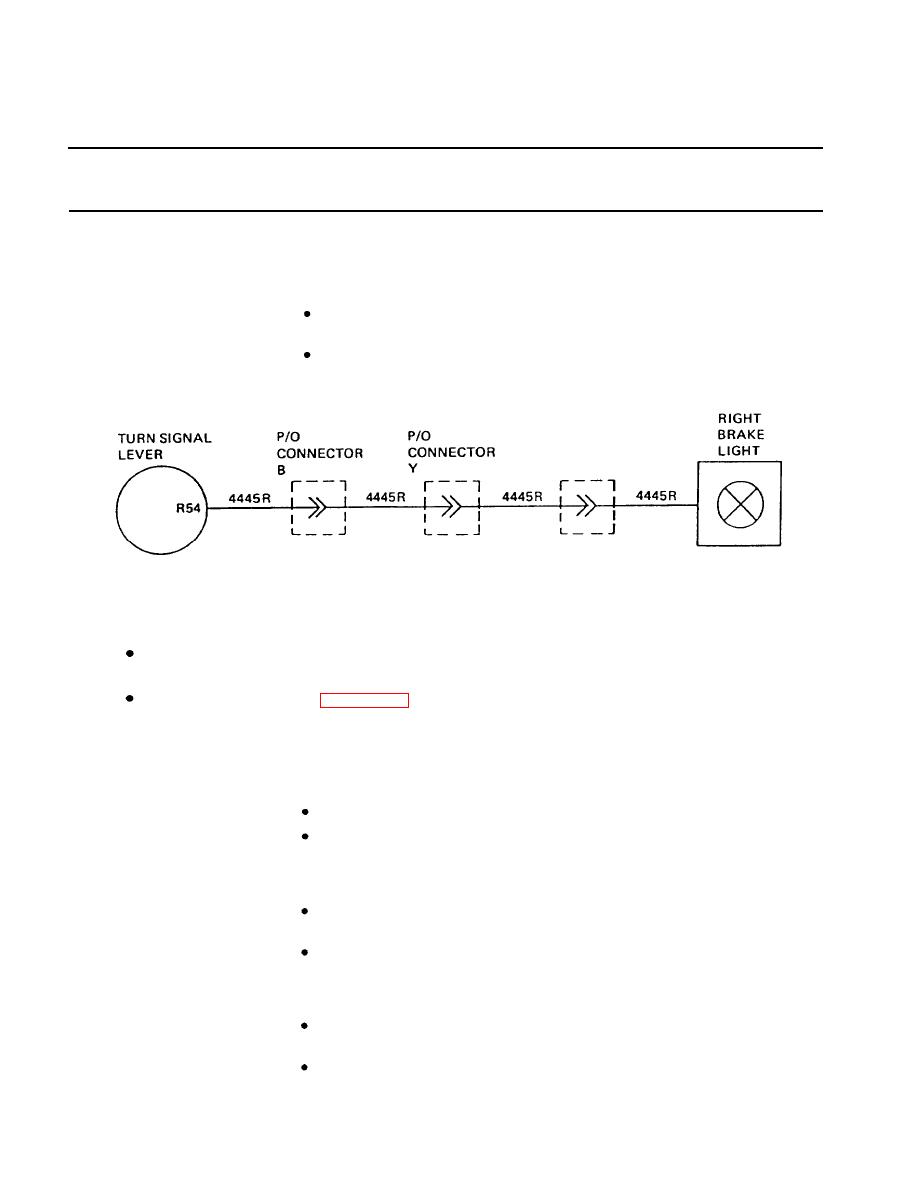
Step 9. Check for +24 VDC between wire 4445R (11) and ground at right brake
light connector (17).
If +24 VDC is present, replace rear composite stoplight/taillight
(page 4-190).
If +24 VDC is not present, repair wiring 4445R between brake
light connector and connector Y.
62. RIGHT TAILLIGHT WILL NOT LIGHT.
NOTE
Vehicle MASTER disconnect switch must be ON and master light switch set to
STOP LIGHT. Failure to do so will cause erroneous results.
Refer to wiring diagram (page 3-196) for all wiring repair steps.
Remove two screws (1), two washers (2), and guard (3). Loosen six screws
Step 1.
(4) and remove retainer (5).
Step 2. Remove right tail lamp (6) and check for continuity.
If there is no continuity, replace lamp.
If there is continuity, go to step 3.
Step 3. Disconnect connector B (7) and check for +24 VDC between wire 41TR (8)
and ground.
If +24 VDC is not present, repair wiring 41TR between
connector B and fuse box 2.
If +24 VDC is present, reconnect connector B and go to step 4.
Step 4. Disconnect connector Y (9) and check for +24 VDC between wire 41TR (8)
and ground.
If +24 VDC is not present, repair wiring 41TR between
connector Y and connector B.
If +24 VDC is present, reconnect connector Y and go to step 5.
|
|
Privacy Statement - Press Release - Copyright Information. - Contact Us |