 |
|||
|
|
|||
|
Page Title:
oLEFT FRONT HEADLIGHT HIGH BEAM WILL NOT LIGHT. cont'd |
|
||
| ||||||||||
|
|
 TM 5-2420-224-20-1
Table 3-5. Troubleshooting (Cont)
Malfunction
Test or Inspection
Corrective Action
ELECTRICAL SYSTEM (CONT)
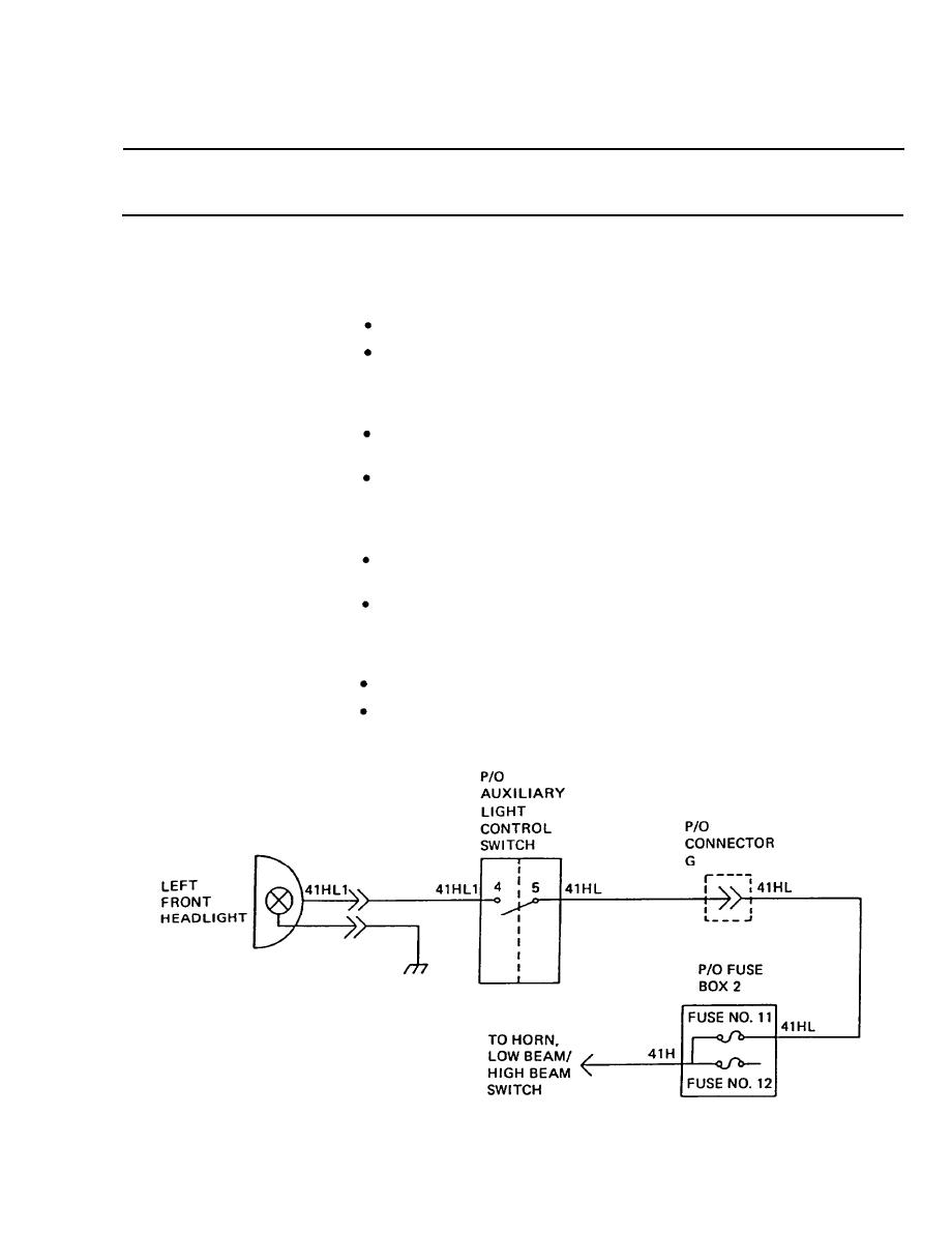
Step 6. Check for +24 VDC between wire 41HL1 (10) and ground at auxiliary light
control switch (11).
If +24 VDC is present, repair wiring 41HL1.
If +24 VDC is not present, go to step 7.
Step 7. Check for +24 VDC between wire 41HL (12) and ground at auxiliary light
control switch (11).
If +24 VDC is present, replace auxiliary light control switch
(page 4-146).
If +24 VDC is not present, go to step 8.
Step 8. Disconnect connector G (13) and check for +24 VDC between wire 41HL
(12) and ground.
If +24 VDC is present, repair wiring 41HL between connector G
and auxiliary light control switch.
If +24 VDC is not present, reconnect connector G and go to
step 9.
Step 9. Check for +24 VDC between wire 41HL (12) and ground at fuse box 2 (14).
If +24 VDC is not present, replace fuse.
If +24 VDC is present, repair wiring 41HL between fuse box 2
and connector G.
3-109
|
|
Privacy Statement - Press Release - Copyright Information. - Contact Us |