 |
|||
|
|
|||
|
Page Title:
Section I. DESCRIPTION AND USE OF OPERATOR'S CONTROLS AND INDICATORS |
|
||
| ||||||||||
|
|
 TM 5-2420-224-10
Section I. DESCRIPTION AND USE OF OPERATOR'S CONTROLS
AND INDICATORS
Do not attempt to operate the SEE/HMMH until becoming familiar with the location and use of all controls and
indicators. The following pages describe the controls and indicators in use.
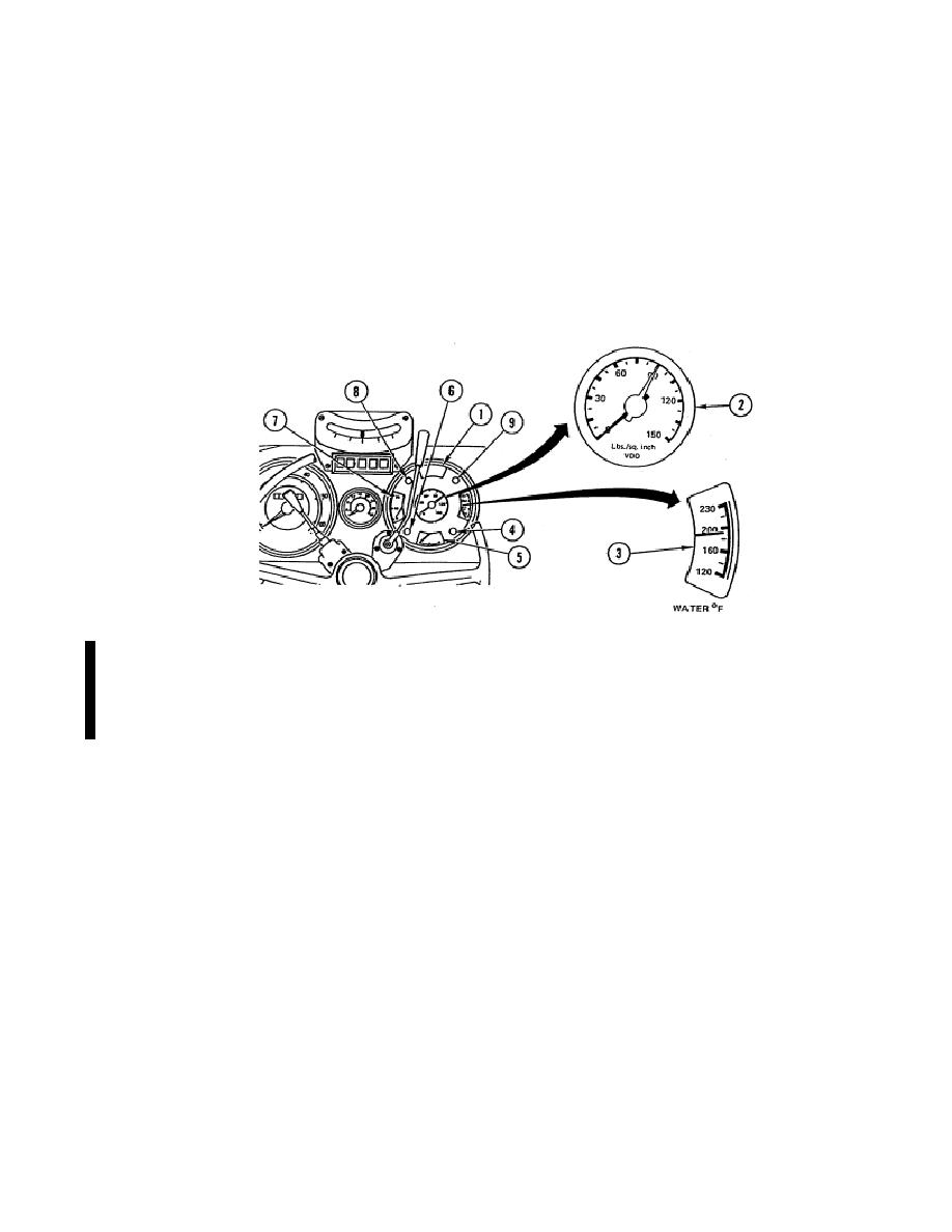
a. Instrument Cluster.
(1)
Low Air Pressure Warning Light (1). Indicates system air pressure is low.
(2)
Dual Air Pressure Gage (2). Indicates amount of air pressure for brake system and accessories.
The white needle indicates reservoir pressure and the red needle indicates air pressure supplied
to brake booster when brakes are applied.
(3)
Coolant Temperature Gage (3). Indicates engine coolant temperature.
(4)
Charge Indicator Light (4). Indicates insufficient charge to battery.
(5)
Fuel Gage (5). Indicates amount of fuel in tank.
(6)
High-Beam Indicator Lamp (6). Indicates headlights are on high beam.
(7)
Oil Pressure Indicator (7). Indicates oil pressure during operation.
(8)
Turn Signal Indicator Lights (8 and 9). Indicate operation and direction of turn signal system.
Change 1
|
|
Privacy Statement - Press Release - Copyright Information. - Contact Us |
