|
| |
TM 5-2420-222-34
5-1.
FUEL INJECTION NOZZLES TEST AND REPAIR (Con’t).
e.
ASSEMBLY
WARNING
No open flames, welding, grinding, smoking,
or use of heat producing devices permitted
nearby when using fuel. Fuel burns easily and
fumes
are
explosive.
Keep
battery
disconnected. Failure to observe these
precautions may cause serious Injury or death
to personnel.
Plastic gloves must be worn and kept clean
and lubricated with clean diesel fuel while
working on Internal parts of fuel Injection
nozzle.
En-
sure
that
work
area
Is
exceptionally clean. Dirt and lint will cause
damage, excessive wear, leakage, or clogs to
fuel injection nozzles.
CAUTION
Soak all fuel Injection nozzle internal parts In
clean diesel fuel before assembly. Fuel
injection nozzle Internal parts which have not
been thoroughly soaked in diesel fuel before
assembly will be damaged during test or
operation.
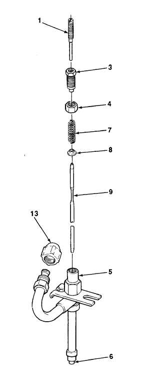
1.
Soak valve (9), pressure adjusting screw (3), lift adjusting
screw (1), spring (7), and spring seat (8) in clean diesel
fuel.
2.
Install dust cap (13) on fuel injection nozzle (5).
3.
Slide valve (9) into fuel injection nozzle (5).
4.
Install lift adjusting screw (1) partway on pressure adjusting
screw (3).
5.
Install adjusting nut (4) on pressure adjusting screw (3) as
far as it will go.
6.
Install spring (7) and spring seat (8) on pressure adjusting
screw (3). Ensure that parts do not fall off.
7.
Install pressure adjusting screw (3) with assembled parts in
fuel injection nozzle (5) and valve (9). Tighten adjusting nut
(4) until snug, then loosen one full turn.
TA701321
5-7
|