|
| |
TM 5-2420-222-20-3
CLUTCH CONTROL VALVE-TO-HYDRAULIC PUMP INLET OIL LINE - CONTINUED
ACTION
LOCATION
ITEM
REMARKS
20.
All metal parts
Look for cracks, breaks, and abnormal bends.
21.
All threaded parts
Look for damaged threads.
ASSEMBLY
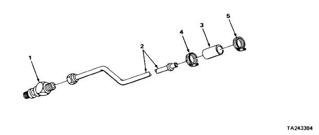
22. Clutch adapter (1)
Oil line (2)
a.
Place clutch adapter (1) in
machinist’s vise.
b.
Screw on to same relative position
noted during disassembly using 1 1/2-
inch open-end wrench.
c.
Take clutch adapter (1) out of
machinist’s vise.
23. Oil line (2)
Hose (3)
Place in position.
24. Hose (3)
Two clamps (4 and 5)
Place in position.
25.
Clamp (4)
Using 1/4-inch flat-tip screwdriver, tighten.
INSTALLATION
NOTE
If oil line mounting brackets and clamps were not taken off during removal, skip
steps 26 thru 29.
2-1357
|

