|
| |
TM 5-2420-222-20-3
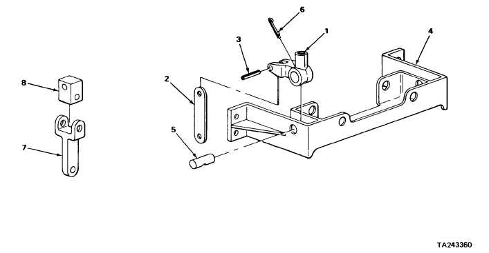
BACKHOE CONTROL VALVE LEVERS AND LINKAGE (SERIAL NUMBERS 235786 THRU 235999 ONLY) -
CONTINUED
ACTION
LOCATION
ITEM
REMARKS
37.
Handle mount (1)
New cotter pin (6)
a.
Place in position.
and pivot shaft (5)
b.
Using long roundnose pliers, bend
ends back.
c.
Repeat steps 33 thru 37 for right
stabilizer control lever linkage.
NOTE
Linkage for both four way control levers is assembled the same way. Backhoe
bucket control lever linkage is shown. Repeat steps 38 thru 51 for backhoe boom
control lever linkage.
38.
Connector link (7)
Universal block (8)
a.
Place connector link (7) in
machinist’s vise.
b.
Coat with grease.
c.
Place in position.
2-1309
|