 |
|||
|
|
|||
|
|
|||
| ||||||||||
|
|
 TM 5-2420-222-20-1
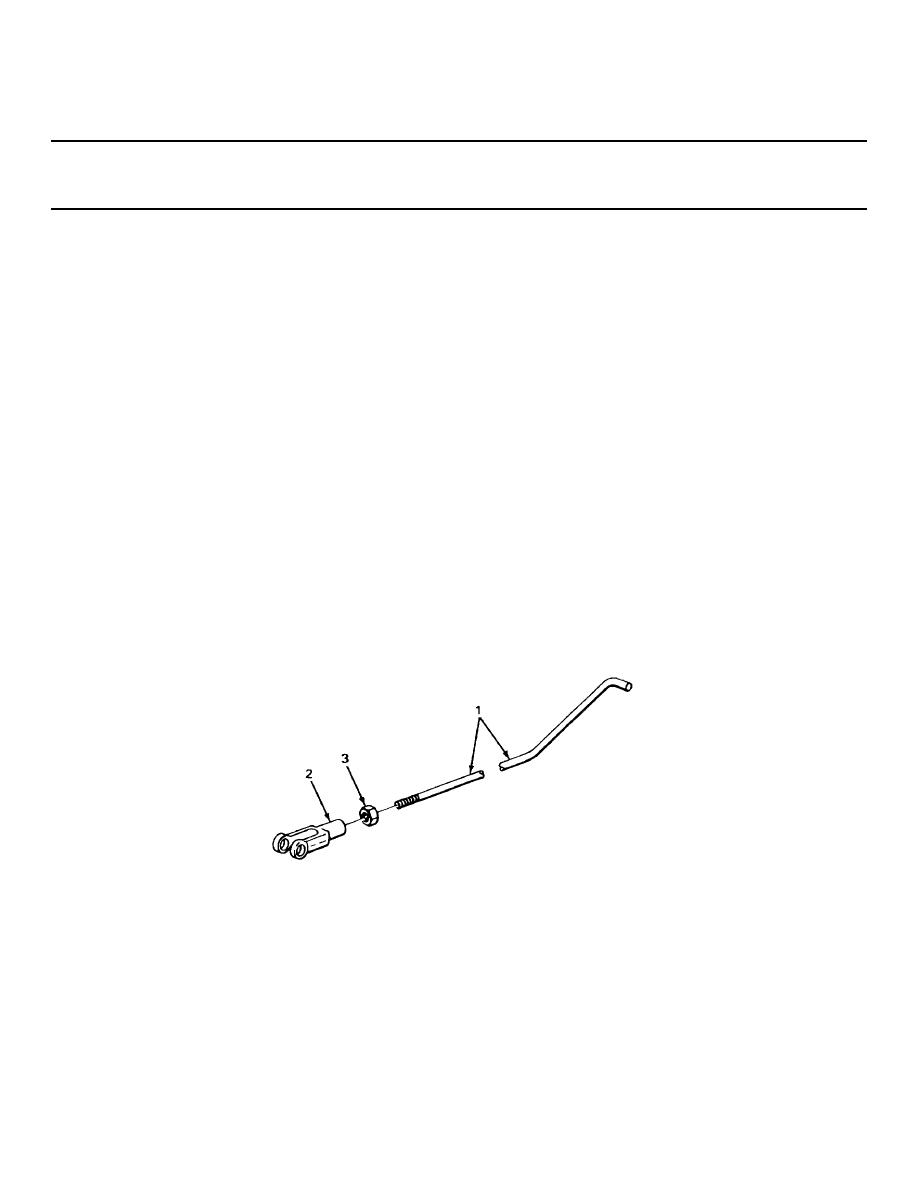
ACCELERATOR PEDAL, FOOT ACCELERATOR ROD, AND SPEED CONTROL ARMS - CONTINUED
ACTION
LOCATION
ITEM
REMARKS
14.
All parts
Look for cracks, bends, and breaks.
15.
All threaded parts
Look for damaged threads.
REPAIR
16.
All threaded parts
If threads are damaged, using screw
except hardware
threading set, restore threads.
ASSEMBLY
17.
Rod (1)
Nut (3)
a. Position rod (1) in machinist's vise with vise jaw
caps.
b. Screw on all the way.
18.
Yoke (2)
Screw on until same number of threads is showing
on rod (1) and yoke (2) is in same relative position as
noted during disassembly.
19.
Rod (1) and
Nut (3)
a. Using 7/16-inch open-end and 0 to yoke
(2)0.760-inch adjustable wrenches, tighten until
seated against yoke(2).
b. Take rod (1) out of machinist's vise with vise jaw
caps.
2-331
|
|
Privacy Statement - Press Release - Copyright Information. - Contact Us |
