 |
|||
|
|
|||
|
|
|||
| ||||||||||
|
|
 TM 5-2420-222-20-1
VALVES - CONTINUED
ACTION
LOCATION
ITEM
REMARKS
8. Continued
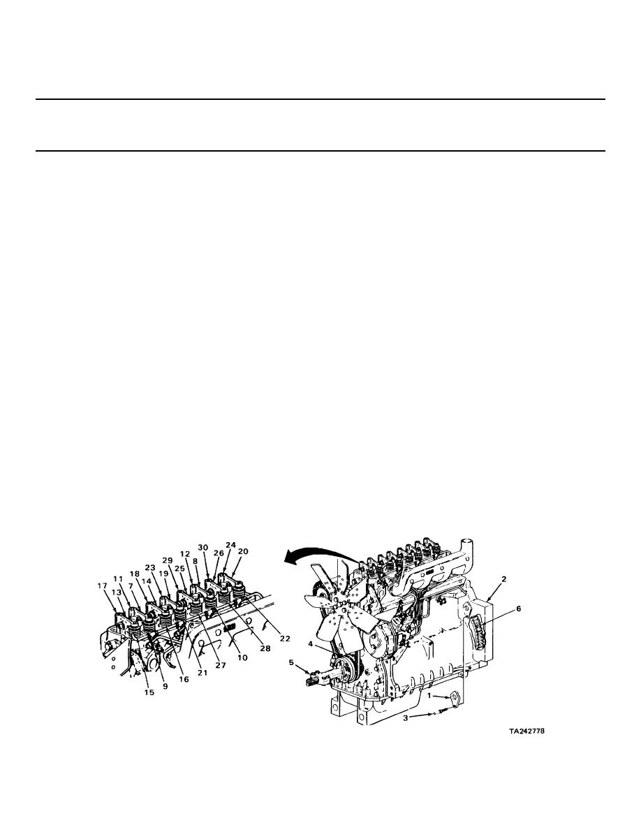
Number four cylinder Is at top dead
center when both of its valves are
fully closed and hole in flywheel is
alined with timing hole in housing;
one full turn of flywheel from number
one cylinder top dead center position.
NOTE
If pin cannot be inserted all the way into flywheel, repeat step 8.
9. Housing (2) and
Pin (3)
Slide through timing hole in housing (2)
flywheel (6)
until seated in hole in flywheel (6).
10. Number two and
Two valves (21 and
While measuring clearance between valves
number four
22) and two
(21 and 22) and rocker arms (19 and 20)
exhaust valve
adjusting screws
with thickness gage, using 1/2-inch open-
rocker arms
(23 and 24)
end wrench, turn screws (23 and 24) in or
(19 and 20)
out as needed to get correct clearance.
Correct clearance is 0.018 inch
(0.46 mm).
11. Number three and
Two valves (27 and
While measuring clearance between valves
number four
28) and two
(27 and 28) and rocker arms (25 and 26)
intake valve
adjusting screws
with thickness gage, using 112-inch open-
rocker arms
(29 and 30)
end wrench, turn screws (29 and 30) in or
(25 and 26)
out as needed to get correct clearance.
Correct clearance is 0.014 inch
(0.36 mm).
2-151
|
|
Privacy Statement - Press Release - Copyright Information. - Contact Us |
