 |
|||
|
|
|||
|
|
|||
| ||||||||||
|
|
 TM 5-2410-237-23
BLADE CONTROL VALVE (LIFT AND TILT) REPAIR - CONTINUED
0245 21
ASSEMBLY - CONTINUED
20.
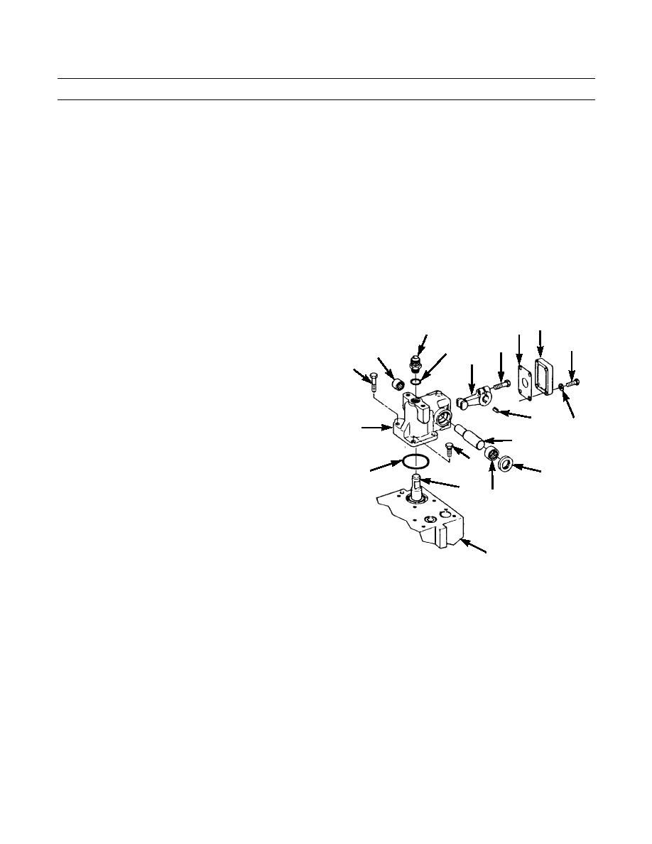
Install new O-ring (76) on adapter (75) and install adapter to control lever housing (63).
21.
Install bearing (74) and new preformed packing (73) on one side of control lever housing (63). Install bearing (72) on
other side.
22.
Install bolt (69) loosely into lever (70).
23.
Insert key (71) into shaft (4) and insert shaft partially through control lever housing (63). Position lever (70) on shaft
over key and push shaft into position in housing. Use soft punch and hammer, if necessary, to seat shaft.
24.
Tighten bolt (69) in lever (70).
25.
Install new O-ring (64) on face of control lever housing (63).
CAUTION
When installing control lever housing, ensure lever (70) is properly engaged in end of spool (88) to avoid a
malfunction and damage to parts.
26.
Position control lever housing (63) on main valve
68 67
75
body (30) over end of spool (88). Install three bolts
65
69
(61) and one bolt (62) to secure control lever housing.
76
72
70
62
27.
Install new gasket (68) and cover (67) on control lever
housing (63) with four bolts (65) and washers (66).
71
66
63
4
61
64
73
88
74
30
421-0065
Change 1
0245 21-10
|
|
Privacy Statement - Press Release - Copyright Information. - Contact Us |