 |
|||
|
|
|||
|
|
|||
| ||||||||||
|
|
 TM 5-2410-237-23
WINCH ASSEMBLY REPAIR - CONTINUED
0245 19
ASSEMBLY - CONTINUED
WARNING
Wear eye protection when assembling clutch assembly. Capscrews on clutch plate are under spring tension.
Install each capscrew a little at a time, in rotation. Failure to follow this warning may result in injury to
personnel.
m.
Install two capscrews (178). Tighten capscrews evenly to compress clutch springs sufficiently to allow plates (177)
to be installed.
n.
Remove guide pins and install plates (177), in same position as marked during disassembly, with six remaining
capscrews (178). Tighten capscrews to 36 lb-ft (49 Nm).
o.
Install plate (176) to hub assembly (184) with eight bolts (175). Tighten bolts in a crisscross pattern to 36 lb-ft (49
Nm).
p.
Repeat steps (a through o) to assemble second clutch assembly.
q.
Install two new O-rings (185) and ball bearings (186) to clutch shaft (155).
r.
Remove six capscrews (178) and two plates (177).
NOTE
Manifold keeps clutch shaft vertical.
s.
Place manifold (156) on suitable work surface.
t.
Install clutch assembly and clutch shaft (155) on manifold (156).
NOTE
Do NOT install capscrews (199) holding bevel gear to clutch housing at this time.
u.
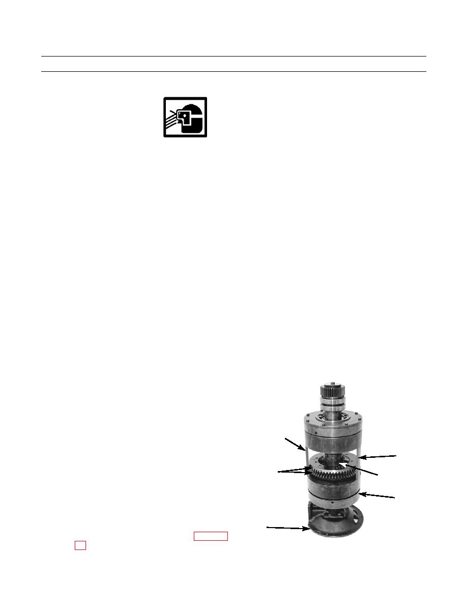
Position bevel gear (200) on clutch housing
(196).
v.
Position second bevel gear (200) on first bevel
gear, with teeth of bevel gears facing each other.
GAGING
w.
Install two plates (177) with six capscrews (178).
Tighten capscrews to 36 lb-ft (49 Nm).
BAR
x.
Install second clutch assembly on clutch shaft
GAGING
(155).
BAR
200
NOTE
155
Finished faces of clutch housings must be
196
7.024 0.002 in. (178.41 0.05 mm) apart.
y.
Move second clutch assembly toward top of
156
clutch shaft (155) and install three 7.023 0.001
in. (178.38 0.03 mm) gaging bars (WP 0244
421-0224
0245 19-23
Change 1
|
|
Privacy Statement - Press Release - Copyright Information. - Contact Us |