 |
|||
|
|
|||
|
|
|||
| ||||||||||
|
|
 TM 5-2410-237-23
WINCH ASSEMBLY REPAIR - CONTINUED
0245 19
ASSEMBLY - CONTINUED
NOTE
Do NOT install new seal (118), new shims (117) or bolts (115) at this time.
k.
Position shaft (125) assembly on bearing cage (116) and set pinion assembly aside.
2.
Install Winch Bevel Gear and Shaft Assembly.
NOTE
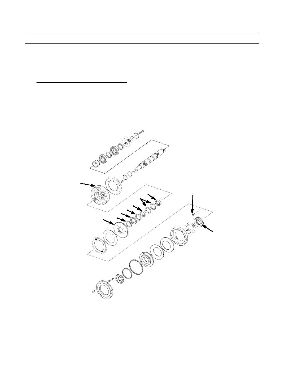
There are two clutch assemblies on clutch shaft. The following steps (steps a through o) describe and illus-
trate assembly of one clutch assembly.
a.
Install bearing sleeves (198) and bearing spacers (197) in clutch housing (196).
b.
Install thrust bearing (195) and washers (193 and 194) in clutch housing (196).
c.
Install reaction plate (192) in clutch housing (196).
196
188
198
197
198
194
195
193
192
189
421-0223
NOTE
If holes will not line up, turn reaction plate over and install manifold again.
d.
Install manifold (189) on reaction plate (192). Align threaded bores in manifold with threaded bores in reaction
plate.
e.
Install manifold (189) with two bolts (188).
0245 19-21
Change 1
|
|
Privacy Statement - Press Release - Copyright Information. - Contact Us |