 |
|||
|
|
|||
|
|
|||
| ||||||||||
|
|
 TM 5-2410-237-23
WINCH ASSEMBLY REPAIR - CONTINUED
0245 19
CLEANING AND INSPECTION
WARNING
Solvent cleaning compound MIL-PRF-680 Type III is an environmentally compliant and low toxic
material. However, it may be irritating to the eyes and skin. Use protective gloves and goggles. Use in
well-ventilated areas. Keep away from open flames and other sources of ignition. Failure to follow this
warning may cause injury or death.
Particles blown by compressed air are hazardous. DO NOT exceed 15 psi (103 kPa) nozzle pressure
when drying parts with compressed air. DO NOT direct compressed air against human skin. Failure to
follow this warning may result in injury. Make sure air stream is directed away from user and other
personnel in the area. To prevent injury, user must wear protective goggles or face shield.
1.
Clean all parts in solvent cleaning compound. Ensure all RTV compound is removed from mounting surfaces of winch
case and access covers.
2.
Thoroughly dry all parts with pressurized air.
3.
Inspect parts for cracks, breaks, distortion or other damage IAW WP 0241 00.
4.
Replace damaged or defective parts.
CAUTION
ASSEMBLY
To prevent contamination of winch, keep work area and components of winch clean.
NOTE
Lightly coat all new O-rings, packing retainer, seal rings and seals with clean oil before assembly.
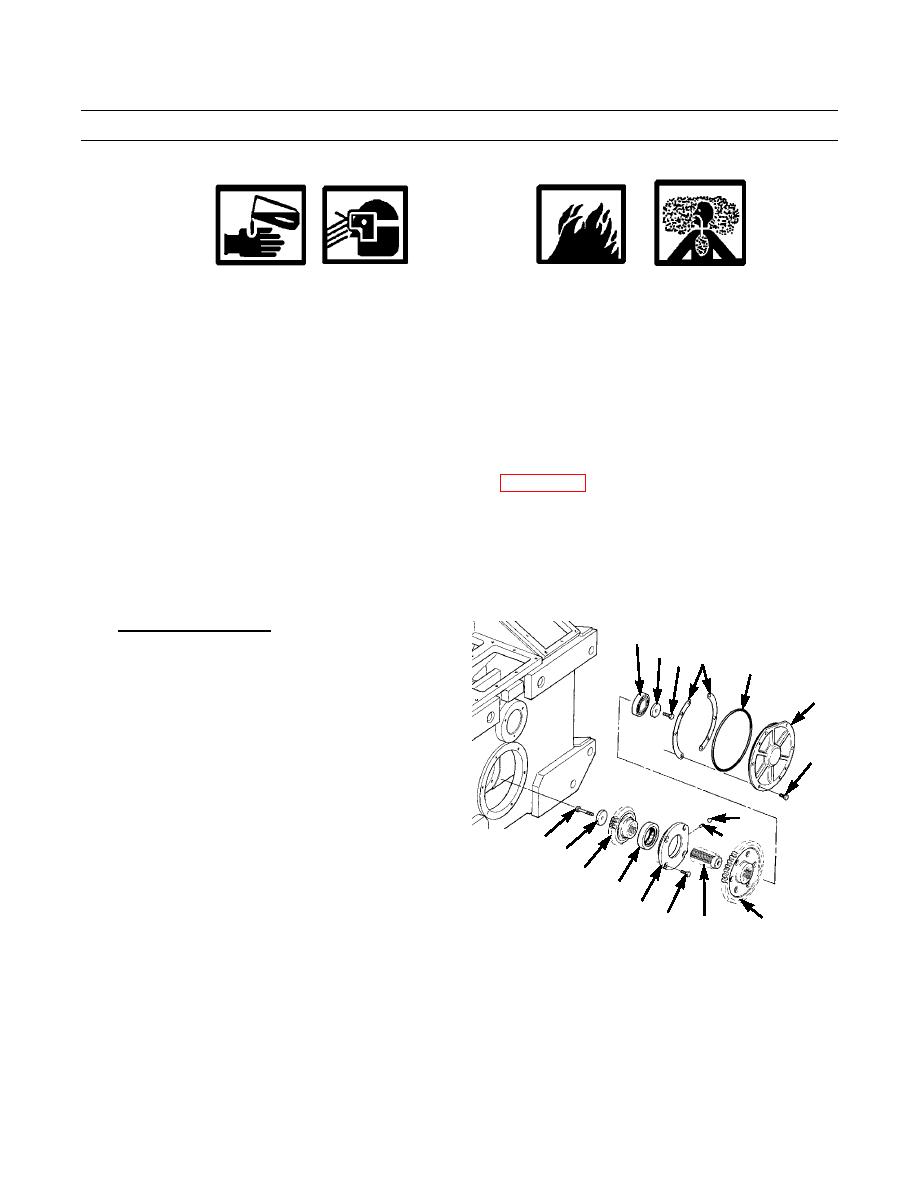
1.
Assemble Winch Pinion.
121
NOTE
120 119
117
118
Winch pinion assembly is required for
adjusting bevel gear and shaft assembly.
116
Therefore, it should be assembled first,
but not installed at this time.
a.
Cool bearing (126) to approximately 32F (0C).
115
b.
Install bearing (126) in bearing cage (124), with
hole in bearing aligned with hole in cage.
c.
Install dowel (131) through bearing cage (124)
130
and into bearing (126).
131
128
d.
Install plug (130) in bearing cage (124).
129
127
e.
Cool shaft (125) to approximately 32F (0C).
126
Position bearing (121) on shaft.
124
421-0217
122
f.
Install washer (120) and capscrew (119). Tighten
123
125
capscrew to 36 lb-ft (49 Nm).
NOTE
Drive gear must be installed with shorter end toward bearing cage (116).
g.
Install drive gear (122) on shaft (125).
h.
Install four bolts (123) and bearing cage (124) on pinion gear (127).
i.
Install pinion gear (127) on shaft (125).
j.
Install washer (129) and capscrew (128) on shaft (125). Tighten capscrew to 36 lb-ft (49 Nm).
Change 1
0245 19-20
|
|
Privacy Statement - Press Release - Copyright Information. - Contact Us |
