 |
|||
|
|
|||
|
|
|||
| ||||||||||
|
|
 TM 5-2410-237-23
WINCH ASSEMBLY REPAIR - CONTINUED
0245 19
DISASSEMBLY - CONTINUED
k.
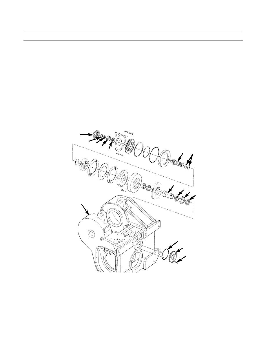
Remove two O-rings (80) from shaft (79). Discard O-rings.
NOTE
Hold input clutch assembly together with wire.
l.
Remove input clutch assembly (78) from case (5). Remove wire. Set input clutch assembly aside for further disas-
sembly.
m.
Remove coupling (81) from case (5).
n.
Remove bearing cone (82) from coupling (81).
o.
Remove three capscrews (83), retainer (84) and O-ring (85) from case (5). Discard O-ring.
p.
Remove retaining ring (86) and carrier (87) from shaft (79).
q.
Remove bearing cone (88) from shaft (79).
r.
Remove bearing cup (89) from input clutch bearing cage (75).
s.
Remove bearing cup (90) and seal (91) from retainer (84). Discard seal.
75
86 87
89
79
88
80
81
82 90
91
5
85
84
83
421-0215
0245 19-11
Change 1
|
|
Privacy Statement - Press Release - Copyright Information. - Contact Us |