 |
|||
|
|
|||
|
|
|||
| ||||||||||
|
|
 TM 5-2410-237-23
TORQUE DIVIDER REPAIR - CONTINUED
0245 14
CLEANING
WARNING
Solvent cleaning compound MIL-PRF-680 Type III is an environmentally compliant and low toxic
material. However, it may be irritating to the eyes and skin. The use of protective gloves and goggles is
suggested. Use in well-ventilated areas. Keep away from open flames and other sources of ignition.
Failure to follow this warning may cause injury or death.
Particles blown by compressed air are hazardous. DO NOT exceed 15 psi (103 kPa) nozzle pressure
when drying parts with compressed air. DO NOT direct compressed air against human skin. Failure to
follow this warning may result in injury. Make sure air stream is directed away from user and other
personnel in the area. To prevent injury, user must wear protective goggles or face shield.
CAUTION
Whenever a torque converter fails, the entire torque converter fluid system must be cleaned thoroughly to
remove all metal chips and particles before the converter is returned to operation. Any foreign material left
in the torque converter will be circulated through the transmission lubrication valve and into the transmis-
sion lubricant circuit, causing recurrent failure.
1.
Clean all parts with solvent cleaning compound.
2.
Remove gasket material from all mounting surfaces.
3.
Dry all parts with compressed air.
INSPECTION
NOTE
Certain tolerances must be maintained in order for torque divider to operate properly. Check the following
tolerances prior to assembly.
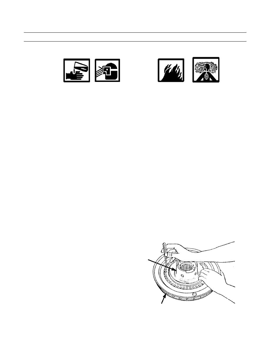
1.
Check clearance between turbine and stator as follows:
a.
Position stator (19) on turbine (31). Hold stator
against one side of turbine and use a feeler gage
to find clearance between stator and turbine.
b.
The clearance across diameters between stator
and turbine must be 0.012-0.018 in. (0.30-0.45
19
mm). Check the clearance at four points on tur-
bine. The maximum permissible clearance across
the diameters is 0.030 in. (0.76 mm).
421-0170
31
0245 14-8
Change 1
|
|
Privacy Statement - Press Release - Copyright Information. - Contact Us |
