 |
|||
|
|
|||
|
|
|||
| ||||||||||
|
|
 TM 5-2410-237-23
TURBOCHARGER REPAIR - CONTINUED
0245 13
CLEANING AND INSPECTION
WARNING
Solvent cleaning compound MIL-PRF-680 Type III is an environmentally compliant and low toxic
material. However, it may be irritating to the eyes and skin. Use protective gloves and goggles. Use in
well-ventilated areas. Keep away from open flames and other sources of ignition.
Particles blown by compressed air are hazardous. DO NOT exceed 15 psi (103 kPa) nozzle pressure
when drying parts with compressed air. DO NOT direct compressed air against human skin. Failure to
follow this warning may result in serious injury. Make sure air stream is directed away from user and
other personnel in the area. To prevent injury, user must wear protective goggles or face shield.
1.
Clean all components and surfaces with solvent cleaning compound.
2.
Dry components with compressed air.
3.
Inspect all components for wear, pitting, cracks or corrosion IAW WP 0241 00.
4.
Replace damaged components.
5.
Inspect oil passages to make sure they are clean and unobstructed.
6.
Inspect oil passages for corrosion, pitting and damage.
7.
Replace components as necessary.
ASSEMBLY
1.
Coat all components with a thin film of clean oil.
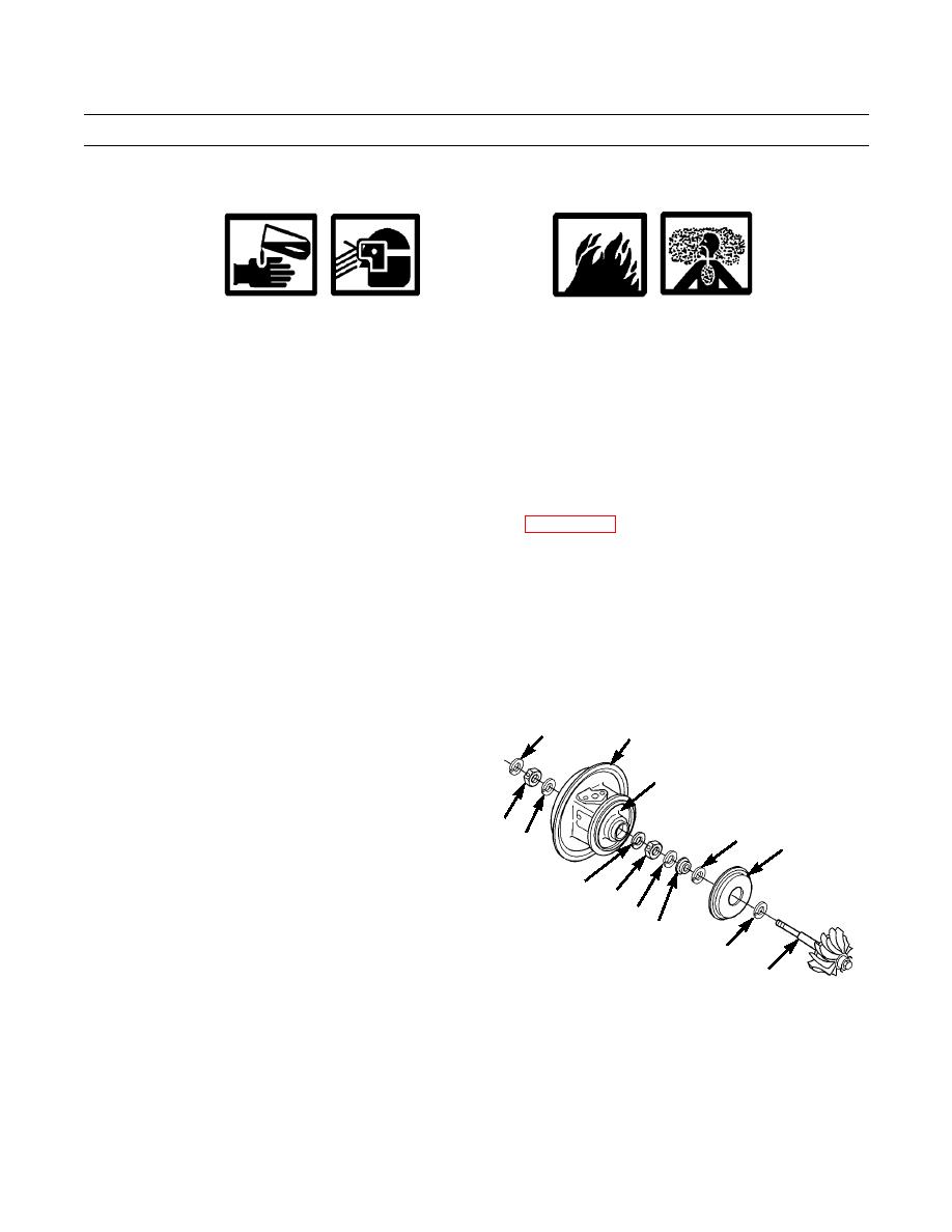
28
2
APPLY HIGH TEMPERATURE
2.
Install snap ring (16) with round side facing out.
GREASE HERE
3.
Install new bearing (15) and snap ring (14) with round
side facing out.
29
12
11
30
4.
Install new sleeve (13) and new snap ring (12).
5.
Install snap ring (30) into cartridge (2) with round side
16
facing out.
15
14
13
6.
Install bearing (29) into cartridge (2). Install snap ring
10
(28), with round side toward bearing, into cartridge
(2).
9
421-0240
7.
Fill seal groove to at least one-half depth with high
temperature grease. Install new seal (10) onto shaft of
turbine wheel assembly (9).
8.
Place shroud (11) on small side of cartridge (2). Install
turbine wheel assembly (9) through small side of car-
tridge (2).
Change 1
0245 13-4
|
|
Privacy Statement - Press Release - Copyright Information. - Contact Us |
