 |
|||
|
|
|||
|
|
|||
| ||||||||||
|
|
 TM 5-2410-237-23
0245 04
INSTALLATION - CONTINUED
NOTE
Make sure the "V" on the piston is in alignment with the "V" on the cylinder block.
3.
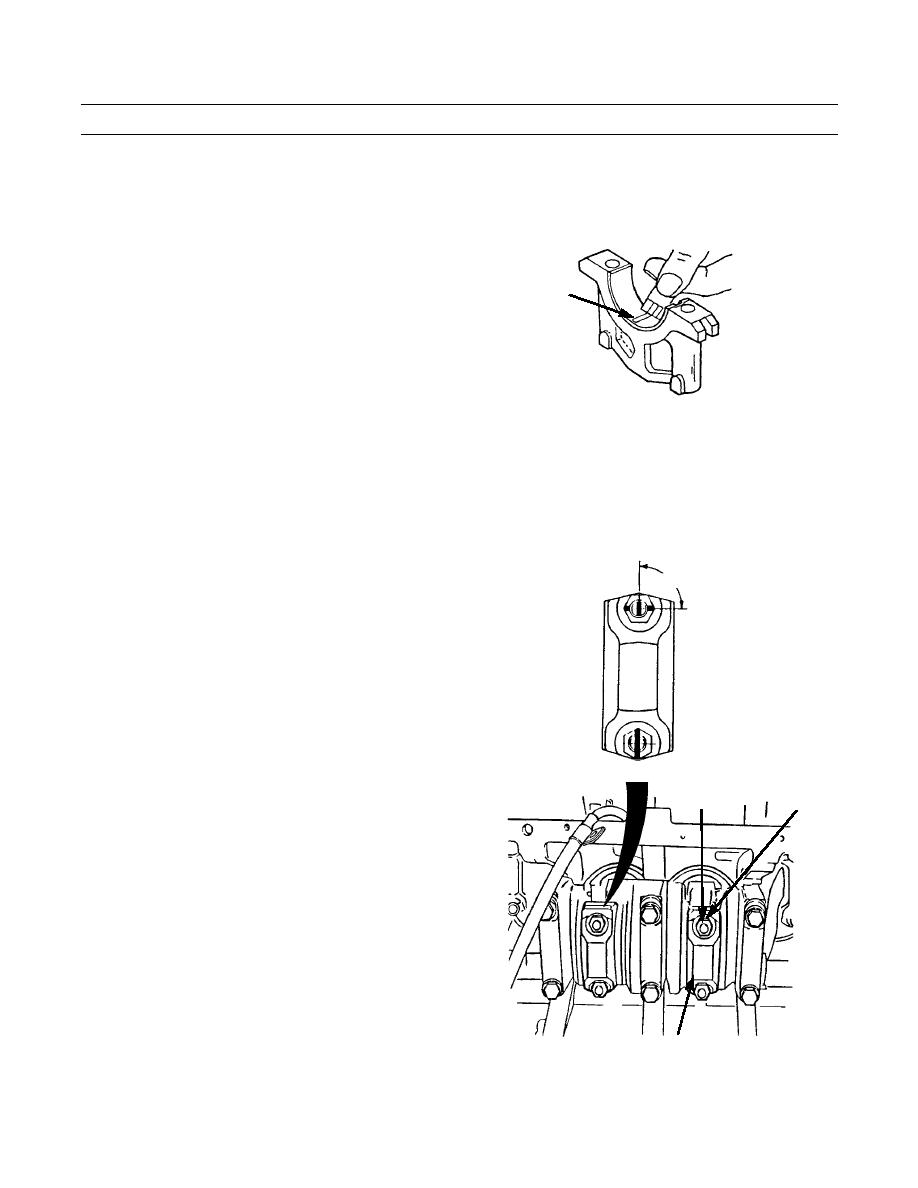
Install a piece of bearing clearance gauge on crank-
shaft journal.
BEARING
CLEARANCE
GAUGE
421-0090
NOTE
When connecting rod caps are installed, ensure the number on side of cap is next to the same number on
side of corresponding connecting rod.
4.
Place connecting rod caps (2) in position. Install the nuts (1) onto bolts (16). Tighten nuts to 27-33 lb-ft (37-45 Nm).
CAUTION
90
Do not use an impact wrench to tighten
connecting rod nuts the additional 90
degrees.
5.
Mark each connecting rod cap (2) and nuts (1). Use a
wrench to tighten nuts another 90 degrees.
6.
Use a wrench to remove nuts (1), then remove con-
necting rod cap (2).
7.
Remove bearing clearance gauge piece and measure
for new bearings; the connecting rod bearing clearance
must be 0.0030 to 0.0066 in. (0.076 to 0.168 mm).
Replace the upper and lower halves if measurement is
16
1
less than 0.010 in. (0.25 mm). Replace bearing cap if
clearance is under the specified measurements.
2,3
421-0108
Change 1
0245 04-10
|
|
Privacy Statement - Press Release - Copyright Information. - Contact Us |