 |
|||
|
|
|||
|
|
|||
| ||||||||||
|
|
 TM 5-2410-237-23
ELECTRICAL GENERAL MAINTENANCE INSTRUCTIONS - CONTINUED
0242 00
RECEPTACLE CONNECTOR REPAIR
1.
While releasing locking tab through front of connector (1), push wire (2) and receptacle (3) through front of connector.
2.
If defective, remove receptacle (3) from wire (2) by cutting through wire just behind receptacle. Discard receptacle.
NOTE
Perform steps 3 through 6 only if receptacle was removed.
3.
Slide connector (1) back on wire (2).
4.
Strip insulation of wire (2) to expose in. (6 mm) length of metal strands (4).
5.
Securely crimp tabs (5) of new receptacle (3) over
1
metal strands (4).
2
4
6.
Crimp tabs (6) of receptacle (3) over insulation of wire
65
3
(2).
7.
Slide connector (1) forward over receptacle (3) until
locking tab of receptacle snaps into place.
387-794
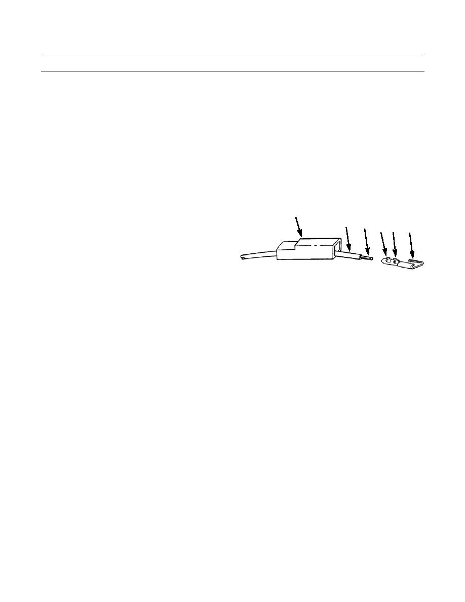
WATERPROOF CONNECTOR REPAIR
1.
Remove end cover (7) and gasket (8) from front of connector (9).
2.
Remove seal (10) from rear of connector (9) and slide seal back on wire (11).
NOTE
Perform the following steps for each wire of connector.
3.
While releasing locking tab through front of connector (9), remove wire (11) and pin (12) through rear of connector.
4.
If defective, remove pin (12) from wire (11) by cutting just behind pin. Discard pin.
NOTE
Perform steps 5 through 8 only if pin was removed.
5.
Strip insulation of wire (11) to expose in. (6 mm) length of metal strands (13).
6.
Insert metal strands (13) of wire (11) fully into rear of new pin (12).
7.
Securely crimp pin (12) to metal strands (13) of wire (11).
8.
Push pin (12) into rear of connector (9) until fully seated.
9.
Install seal (10) on rear of connector (9).
10.
Install gasket (8) and end cover (7) on front of connector (9).
0242 00-2
|
|
Privacy Statement - Press Release - Copyright Information. - Contact Us |
