 |
|||
|
|
|||
|
|
|||
| ||||||||||
|
|
 TM 5-2410-237-23
BLADE CONTROL LEVER AND LINKAGE REPLACEMENT - CONTINUED
0207 00
INSTALLATION - CONTINUED
12.
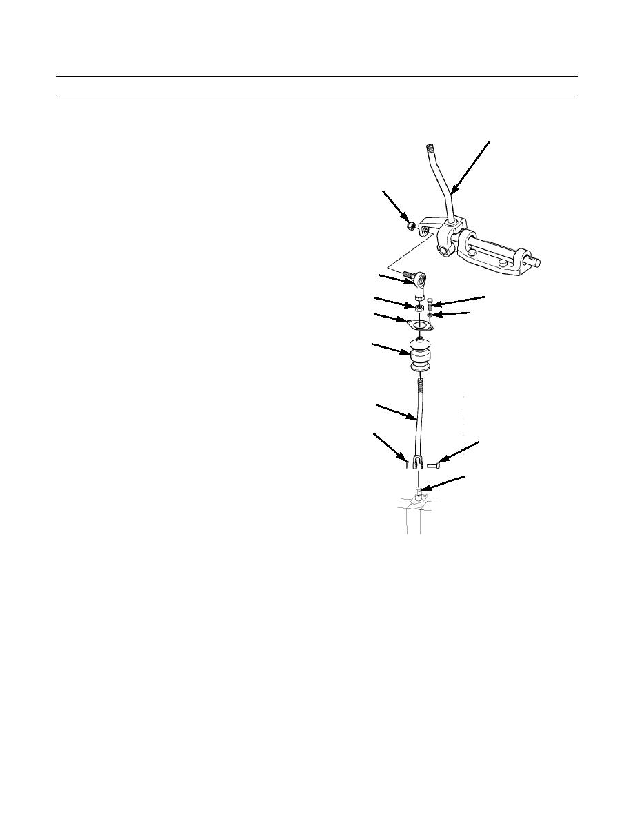
Install boot flange (24) on boot (25) and slide boot
6
about halfway down on rod (26).
13.
Install nut (30) and rod end (21) on rod (26). Do NOT
Tighten nut at this time.
20
14.
Install bottom end of rod (26) on blade tilt pilot valve
(29) with pin (28) and new cotter pin (27).
15.
Slide boot (25) over rod (26) end and secure boot
flange (24) to pilot valve (29) with two washers (23)
and capscrews (22).
16.
Adjust rod end (21) on rod (26) and with blade control
21
lever (6) in vertical position. Install rod end in lever
with new self-locking nut (20). Tighten nut (20) and
22
30
nut (30).
23
24
25
26
27
28
29
387-642
0207 00-8
|
|
Privacy Statement - Press Release - Copyright Information. - Contact Us |